Extraneous Appendage
2011/02/25
The Rans wiring diagram,
while it has been updated over the years, continues to include a fuse on the
regulator that is not specified by Rotax.
Here is how Rans suggests you
wire the regulator: RANS
Note the two fuses that Rans
highlights with **
directing you to see the Rotax diagram for the size of the fuses. One is on the
C line between the regulator and the master bus; the other is on the combined R and B lines before they connect to the battery +ve
at the starter solenoid.
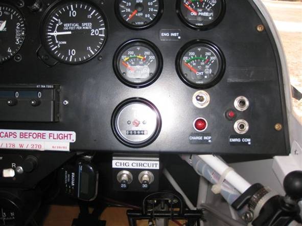
Here is a panel that followed
this diagram. You can see the
the two big breakers on the lower right:
Now take a look at the Rotax
diagram that Rans suggests you go to.
This is how Rotax suggests you wire their regulator: Rotax
Rotax does not have the two fuses. It has one 25
amp fuse on the main power output from the regulator (the R and B).
You can see that the two
middle power output wires (R and B) are joined up with the outer C sense line prior
to going into the single power output fuse. This C line does not flow any
current. Its purpose is to simply read the voltage in the system. Since the
other side of the fuse eventually goes to the battery, the C line gets the
voltage it needs and the power output of the two middle wires gets to the
system through the fuse. Notice that the power goes directly to the main bus
without passing through a switch. The power coming from the battery is
switched.
Here is a simplified version
of the Rotax diagram. I include a 25 amp fuse on the battery output so that the
#10 lead going forward to the main bus is fused.
In my last installation I did
not fuse the power to the starter switch. Master and starter switches were
mounted beside the rear seat. Also did not include the battery disconnect.
The resetting automotive fuses I use are handy in that
they come with mounting tabs and 8-32 posts for wire connectors (and they are a
lot cheaper than the breakers shown above). This makes it easy to hook up the
R, B, C, Capacitor and power to the indicator lamp all on one post on one side
of the fuse and the cable to the master bus on the other. Here is a picture of one:
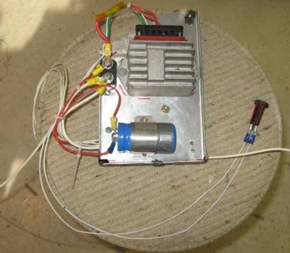
From the regulator connector,
the two red are the R and B, green is C and white is L. The white L line goes
down then off the right side to the lamp; the the second white line on the
right from the lamp connects up with the green at the fuse. The other side of
the fuse goes to the master bus which is on the other side of the plate.
Because Rans puts the starter solenoid with
its 12V supply near the regulator on the firewall, it is convenient to dump the
regulator output there and have it permanently connected to the battery. You
can see, however, that Rotax does not do it this way. Rotax has a direct
connection to the master bus and the battery power through a switch to the bus.
The other difference I have
with the Rans wiring is that it would appear that they use the voltage on the
Lamp, L line to drive the hour meter. I don’t know if it could do both but my
preference is to wire in the charging indicator lamp as per Rotax because it is
a very useful device in that it shows when the system is charging and if you
have left the master on after shutdown.
I am not an electronics guru,
so if someone can spell out why Rans deviates from what Rotax suggests and puts
in the additional fuse, I would greatly appreciate it but until I hear otherwise
I will continue to leave this guy out and wire as per Rotax.
pcowan41 at bell dot net