Geometry of Float Rigging
2014/06/28
CG method update 2014/06/09
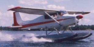
(Homebuilt 170/180hp on
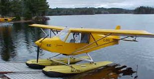
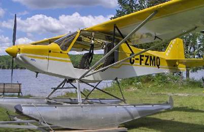
This information is relevant and accurate for light wing loading and low stall speed aircraft such as the 1200lb gross Rans S6 and 7, however, the same considerations were used in rigging the homebuilt 170 on 2425 Edo’s shown above.
To position a set of floats
on an airframe we need to decide on four measurements:
1.
The distance between the
floats;
2.
The height of the airframe
above the floats
3.
The angle between the
centerline of the airframe and the bottom of the float.
4.
The fore/aft position of
the airframe on the floats and with Lotus floats, where to position
the spreader bars/tubes;
See
New Rule
First, Centre to Centre width.
If you look at successful
float installations it is reasonable to conclude that the first two are based
on personal preference and what look the builder wants. There is a range of
float center to center distance of from 40 to 50% of float length. My Murphy
1500 floats (174”) came with a width of 48%; I cut them back to 80” or 46%.
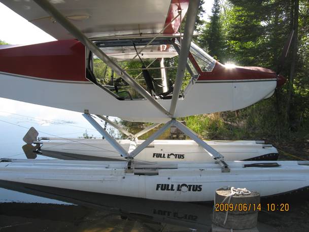
Many 1260 Full Lotus are
mounted at 72” which is 44%; My 1350 LAS floats came with a width of 41% but I’ve lengthened the spreaders to 77” or 46%.
A wide stance will improve
cross wind stability but will make standing near the side of a tandem fuselage
more difficult.
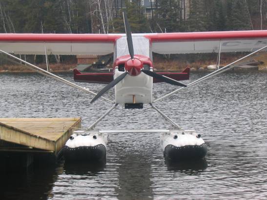
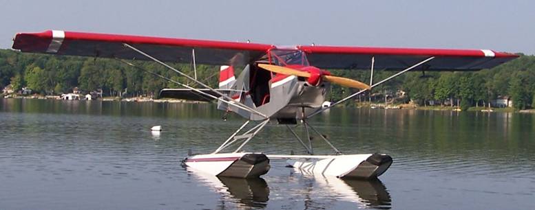
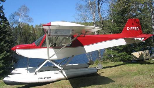
This S6 on Czech amphibs has
a 75” width (and 20” height). Because it is a side by side plane with a wider
fuselage the owner feels the struts look too vertical but it still works just
fine. Also the attachment points to the floats are on the spreader bars so that
further narrows the apparent stance of the struts.
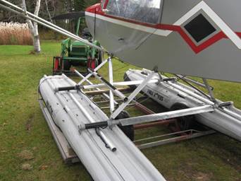
The 1450 Lotus floats
described further down in this write up have a different looking geometry and a
centre to centre distance of only 66” or 40% of the length on this Rans S7.
Whereas these 1260 are 73” centre to centre:
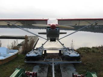
One final point
about width between the floats is related to the size of the dolly you might
want to use to pull the plane out of the water. Narrower measurements might
eliminate some of the rigs out there that are being used on certified
aircraft. The trailer shown above needs
about 46” and that would mean it would not handle the 1450’s above with 66” CC.
Height of fuselage above floats.
This measurement also seems
to be highly related to personal preference. Yes, you need to keep the prop
away from the water but most installations result in the prop tip being much
further off the water than the minimum 12”,
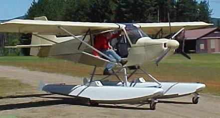
My first Rans S7 was mounted
at about 16” above the floats like this and it swung a 72” prop:
It flew well (except for some
typical Lotus porpoising) and was very easy to get into without the need for a
step on the struts but certainly lacks “dock appeal”.
One of the highest mountings
is on Murphy Rebels where the company rigging shows 31.5” for the fuselage
above the floats. One experienced Murphy guy uses 29”.
This Rans S7 on Czech amphibs
is at 20”
So, with all this in mind, I
went with 80” width and 24” height on these Murphy 1500 on my Rans S7:
There is also some
correlation between height above the floats and step position when you adopt
one approach to positioning the step which will be discussed later.
Angle between datum and floats.
An interneter from
Frey points out that for best
take off performance we want the wing at the angle of attack for maximum lift
while the floats are riding in the water at an angle for minimum drag. He
suggests that a flapped wing needs 14 degrees (this is not true for all
airfoils but close) so the geometry has to provide this. So, how do we achieve that 14* angle of
attack?
First we need to use the
horizontal datum line of the aircraft as the reference line for rigging the
floats. Next, most designers have built in a positive angle of incidence of the
wing center line to the datum line of 2 to 3 degrees. Let’s use three for now.
Frey points out that early
studies showed floats need to ride at 8 degrees for minimum resistance while
planing. Thus, if we mounted the floats
parallel to the datum line we would have an angle of attack of 8 + 3 or 11
degrees when the aircraft is on the step. So, we need to mount the floats at 3
degrees negative to the datum line to get our 14 degrees.
A knowledgeable friend
determined from studies of similar airfoils that my Rans S7 actually achieves
max lift at 18 degrees. This would require not 3 degrees between float and
datum but 7. I have mounted the floats a little more than 3 degrees and
takeoff, cruise and landing performance is excellent; the best performance I’ve
had over four different S7 float planes.
I would predict that cruise
speed and landing characteristics would suffer with more angle
between float and datum. The compromise here is that we don’t want the nose of
the floats too low while in level flight to increase drag or to make it
difficult to achieve a slight nose up position of the floats on landing. While I will experiment with this in the
future, for now, 6 degrees between float and wing CL works well.
When I was
installing 2425
Finally, where to position the airframe on the floats
(Usually looked at as the fore/aft location of the step)?
June 2014 update:
New Rules
After many years and several
unique installations I now propose a major change in conventional thinking.
What I now believe is that we
should just forget about the step, ignore it, don’t even consider where it ends
up because where it actually is is of little consequence and we do not need to
consider it in locating the relative position of the floats on the airframe.
Read the above heading again
but now change it to “Where to position the floats on the airframe”.
So, how do we do that? The
answer is quite simple:
Position
the floats such that the weight of the floats does not change (significantly)
the empty CG of the plane when on wheels
In other words determine the
location of the CG of the complete float and rigging package when off the plane
then mount that CG in such a position that with the wheels removed and the floats
added, the resulting CG is about the same. You will do
this with a couple of trys using your weight and balance spreadsheet.
Only two issues are
important: 1- Maintaining the appropriate CG of the airplane and 2- Loading the
weight of the airframe onto the float near the
If you still aren’t convinced
think about this:
Does the step position affect
flight characteristics? NO
Do all fast boats have a
step? No
Does CG affect flight? Duh
Does loading a boat too far forward
or aft affect getting up on plane? YES
QED
If you do go ahead and read
some of the theory below and think about the opposite concept of loading weight
(the airplane) on the float ( how EDO did it), and assume that the C of G of
the float is near the C of Buoyancy of the float, then this method meets that
requirement as well. If you disagree,
please tell me why this method won’t work.
Back to traditional thinking:
If you ask the average AME
who has had experience installing certified floats where to position floats on
a homebuilt, he likely won’t have much info for you. His experience has
typically been to get a set of rigging made by the float manufacturer for one
specific airframe and bolt it together. He has not needed to know much about
the geometry.
Usually,
if the aircraft type has been mounted on floats in the past you can find out
what worked and copy it. But suppose we cannot find such information, then how
would we proceed? Also, how do we know
if what someone else has done results in the optimal configuration?
One
well known float guy in the Rans world puts the step at 51” aft of the
firewall. For that aircraft, the CG range is 46 to 50.25. Why does this work?
Is it the optimal position?
Based
on what
While most float mounting
instructions have the airframe positioned with the centre line level (an
in-flight attitude) and the floats angled down, the
The discussion of angles
above deals with the transition to flight, in cruise and landing attitude, none
of which has much bearing on the position of the step. The loading of the
floats by setting an airplane on them could be compared to loading a boat. The
small outboard sitting at the dock rests at a specific, more or less level,
probably a bit nose up, attitude. If we are loading several people into the
boat, we position them not all at the front or all at the back but more or less
evenly distributed to retain that level attitude. I suggest we are loading the
boat by distributing the weight equally around the C of B.
Most floats sit in the water
with some nose high attitude Frey says maybe 3 degrees (although the two sets
I’ve installed are at 4.5* to water).
You need to make a drawing to
see the impact of this:
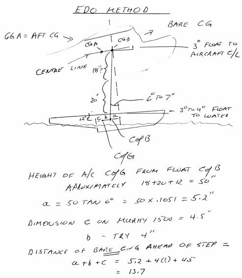
This drawing illustrates
several points.
The weight of the bare
airframe is positioned above the C of B of the float as it sits in the water. The
keel of the float is inclined about 3 degrees from level and the aircraft
centre line is inclined at 3 degrees to the float so the aircraft centre line
is inclined at 6 degrees to the water. It is also true that there is a 6 degree
angle between a line perpendicular to the fuselage centre line and the line
drawn through the C of B.
The distance that the bare,
empty CG is ahead of the step is the sum of
a + b + c. “c” is how far the C
of G of the floats is ahead of the step and we can determine that. On my Murphy
1500 that distance is 4.5”.
Based on knowledge of the ratios of surface
area to volume, I would bet that the C of B is significantly ahead of the C of
G (this is length “b”). Suppose we estimate that the Cof B is another 4” ahead
of the C of G.
We can calculate the length
of line “a” by estimating the distance the aircraft CG is vertically from the float C of B. With the estimates from the
drawing, you can see that the distance “a” is 5.2”
That puts the step 4.5 +4 +
5.2 = 13.7” aft of the bare CG which for
one S7 was 44.7” giving a step location of 44.7+ 13.7 = 58.4”. So even if my
estimate for the distance that the C of B is ahead of the C of G is way off and
we reduced it to zero, we still have 54.4” for step position in this example.
So, what do we use: 51”, 54”
or 58”??? Especially with a tandem
seating aircraft you may have to decide what loading you want to rig for. In
the case of the 54” choice, with full tanks and just the pilot the plane will
climb up on the step, level off and fly off the water with the stick neutral.
With a 200lb passenger, considerable forward stick is needed to get the plane
over on the step. If this aft loading were most typical for me I might be
better to go even more than the 54” but since I’m more often alone I’ll leave
it at 54.
Frequently in discussions of
float positioning, when CG is referenced, it is not clear which CG is being
used. Some rigging instructions for the
level attitude method use the most aft CG limit; usually which CG being used is
not defined. You have to keep in mind what CG is being discussed.
The CG Method
This is a totally different
view of the problem which only looks at weight of the floats on the airframe.
One important point here is
that you should always weigh the floats
when they are rigged and calculate their CG
to use in the work up of the new aircraft CG after adding the
floats. Knowing the float CG lets us
choose this other method for obtaining the fore/aft position. Why not forget
about where the step goes and hang the floats on with the float CG right at the
aircraft empty cg on wheels? This way we are not changing the empty CG when on
floats and what we are used to in
loading the aircraft still applies when we go to floats. Let the step then sit wherever it ends up as
a result of the float design
This is the approach the PG
float manufacturer uses and it works. With PG 1400 floats their CG is about 12”
ahead of the step. The Rans S7 I’m mounting them on has an empty Cg of about
73/46” (aft of prop hub/aft of firewall). This will put the step quite far aft
at 85/58” from the datum. (compared to
that popular 51”!)
If you are interested in some
comments on Pierre Girard and his floats see: pgfloat
Earlier I mentioned that the
horizontal distance of the step from the cg is related to how high the plane is
above the floats.
Visually slide the floats
closer to the plane in the above diagram. As you do that, length “a” gets
smaller which means that the sum of a, b and c is less, thus the step moves
forward along a line parallel to the
aircraft centre line relative to the CG. If you lower the floats and
thus increase the distance to the C of G of the plane, the step moves further
back from the CG. This means that it is
not enough to say where the step is horizontally without also giving the height
of the aircraft above the floats. Or looking at it another way, that S7
pictured above with the fuselage only 16” above the floats will handle
differently from the one with the fuselage 24” above the floats with the step
at the same distance from the CG.
After posting this site to
the Matronics Seaplane list, Hagen Heckel from
In reality, the precise step
position is not critical. For example, on the Rans S-7S, the aft CG limit is
50.25”. One float guy in
It is likely that for a fully
load aircraft the more forward fuselage position called out by Edo (and
Germany) will allow a faster climb up onto the step than would be the case with
the weight further back (the boat analogy illustrates this too). With lightly
loaded aircraft this would be less noticeable.
With this in mind, I moved
the step on the 1350 floats to 5” aft of CG. This also seems to work fine. With
a 220lb person in the back seat, the heal of the float submerges slightly when
I also stand on the float beside the rear seat, so I am going to move the
fuselage another inch forward. Why not
if fluid dynamics is the only issue? Yes overall CG is still fine.
These floats have a unique M
shaped bottom forward of step. They appear to accelerate more quickly as they
get on the step but ride noticeably harder on waves than a straight V bottom.
Lotus floats have less of a
rise from the step aft so the S-7S below is mounted at 4.5 degrees to the float
top so that little rotation is required at lift off. The wide angle is
noticeable but they are still faster in cruise than a set of Murphy 1500’s that
were on the plane previously.
The step is also further aft
to provide more rearward flotation when loading because these floats tend to
have minimal rear end flotation.
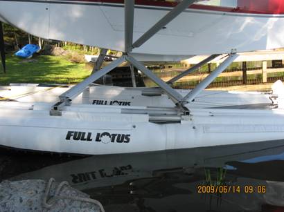
Some thoughts on
Lotus Floats
First, I should point out
that, overall, I have been a proponent of Full Lotus floats for years ever
since I bought my first Rans S7 on 1260’s in 2003. In fact, the company has
used my testimonial on their site:
(Full Lotus floats are
terrific. They can take a lot of abuse from rocks or shallow water and handle
really well.)
and Aircraft Spruce has a
picture of one of my ex planes on their Full Lotus page.
However, after the 1450
floats came out I did have some reservations due to their unique proportions
and found the company somewhat reluctant to provide technical info.
General comments:
These “air bag” floats
perform quite well and have advantages over other materials which include:
Less easily damaged when beaching,
Provide some shock absorbing on a hard landing,
Quite useable in the winter and more maneuverable than
skiis,
A puncture may be easily repaired temporarily and will
affect only one bladder of the 8,
No pump out required.
The disadvantages are that
they do take on a small amount of water inside the bladders which have to be
drained at least annually and the air pressure must be monitored frequently due
to temperature changes. While they tend to be inexpensive, they do have a
limited life. Also, they do not provide as solid a surface for standing on as
other designs.
Here is a link to a video on
draining the floats: http://www.youtube.com/user/kitfoxflyer
For more thoughts on the pro’s and more con’s
of these floats see Dave Loveman’s site:
http://www.ultralightnews.com/lotus1/lotus.html
While Dave makes some good
points, I would disagree with a couple of things he says. For example he feels
that: “1260 floats do not have enough
floatation in the front section of the float for most two place, tractor
aircraft.”. It is not reasonable to make this blanket statement
without specifying the gross weight of the aircraft. From my experience aircraft like the early
Rans S7 at 1200lbs gross and 625 to 675 lbs empty, work fine on the 1260
floats.
Dave also suggests that the
configuration of the aircraft and the position of the significant weights such
as engine, pilot and passenger have a bearing on float performance. He says:
“In most pusher configuration
aircraft the weight put on the craft is distributed over the full length of the
float.” And: “On a tractor aircraft the
full weight of the engine sits on the front section, with two pilots and full
fuel normally located near or on the middle area of the float.”
My understanding of the
physics of this is that the only crucial issue is where the C of G of the
aircraft is positioned on the floats. The floats only see this CG weight and
they “know” nothing about how it is distributed in the airframe. Thrust lines
could make a difference but not whether or not the engine is up front.
Position of
spreader bars/tubes.
Most rigid floats have the
spreader bars positioned more or less equally ahead and behind the step.
This also seems to work fine
with Lotus floats but occasionally you see variations. These 1260 floats have
the spreaders much further forward, perhaps to suit the location of hard points
on the airframe but this setup does result in some additional flexing of the
stiffener tubes. Perhaps a third, partial stiffener should be added.
The 1450 installation below
also has the spreaders further forward but they do come with pockets for the third
stiffener and the tail section is shorter than the forward section (and shorter
than the aft section of 1260’s) so has inherently more stiffness than with the
1260’s above.
Here are 1260’s with a 3rd stiffener:
Why focus on the
1450?
Until recently there were
three sizes of Lotus floats in the light aircraft range: 1220, 1260 and 1650.
Clearly there was a large gap between the 1260 and 1650. The 1260 are a
satisfactory size for 1200lb gross weight aircraft like the earlier Rans S7 but
as mentioned above, the 1260 floats could use a little more flotation in the
heels and are a little small for 1300lb gross aircraft. Now that it is common to see the S7S at 750
lbs empty, the 1260 is a marginal choice yet I suspect many people would feel that
the 1650 was too big a float (although it may not be).
The 1450 model fills that
gap. But it turns out that the 1450 is not an enlarged 1260 with proportionate
increase in all dimensions. The company was quite creative and expedient in the
way they came up with this higher displacement float with an unorthodox shape
and as a result have generated some questions which they were more or less
unwilling to acknowledge let alone discuss informative answers.
To create the 1450 they used
the longer front end from a 1650 mated to the shorter heel of a 1220. In other words, compared to the
1260, we have a bigger front end with a SMALLER rear end with the result that
the step is far aft of the mid point of the float.
Apparently the
cross sectional area of the 1260, 1450 and 1650 forward tube is the same; just
the lengths vary.
Here is a chart
showing the dimensions of the floats taken from earlier measurements on the
company web site where the 1450 numbers are derived from the 1220 and 1650
diagrams: (currently the specs on
the Lotus site are slightly different)
|
FLOAT |
LENGTH |
FORWARD |
AFT |
FWD/AFT X SECTION, STEP % |
|
1220 |
148 |
82 |
66 |
16x28 /
5x20 55% |
|
1260 |
166 |
82 |
84 |
16x27.5 /
4x18.5 49% |
|
1450 |
163 |
97 |
66 |
16x27.5 /
5x20 59.5% * |
|
1650 |
181.5 |
97 |
84.5 |
16x27.5 /
5.5x22 53% |
You can see from the above
that the cross sectional area of all of the forward sections of these floats is
approximately the same so overall bulk does not change just the lengths.
I’ve cut out some scale side views of these
floats based on the above dimensions to illustrate the differences between the
floats (top -1450, bottom - 1260):
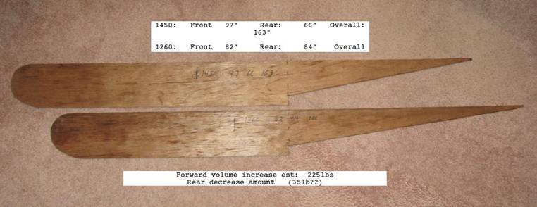
These cutouts show how the
added length at the front contributes significantly to the increased flotation
(1260 to 1450 = 190lbs) but also that the heal of the float aft of the step is
much smaller (a rough calculation yields maybe 50 lbs but based on Lotus
numbers it is closer to 35).
This superimposed view shows
the heel volume difference with the 1450 having the smaller volume:
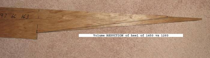
The patterns taper to a
sharper point than the actual dimensions would suggest because there is also a
narrowing of the float from side to side and the objective is to represent the
comparative volume. Since the actual measurements mentioned above show a
slightly thicker and wider tail end on the 1450’s, the pattern above should be
just a little larger at the tail end. The length difference, however, is
correct so that the decreased aft volume does still exist.
What this means is that if
1450 floats are replacing 1260’s and if they are mounted with the step at the
same position (since most people use the step as the significant reference
point) then there will be LESS flotation at the aft end even with these larger
floats. Clearly, mounted this way, they will make the aft flotation issue worse.
When asked about mounting these floats (as I did a couple of years ago) the
company’s response was: “they are mounted the same as the 1260” yet clearly
this will result in too little aft flotation and doing so would seem to
contradict the significance of the C of B as discussed above..
On most floats the step is positioned
at close to the mid length point of the floats with the Centre of Buoyancy
typically a few inches ahead of the step (like it is on the 1260). Earlier I
mentioned the importance of the C of B in rigging the floats. While we tend to use the step as a reference
point, it is really the C of B position relative to the aircraft CG that is
critical (based on the material from Edo Corporation, see details earlier in
this page).
Now suppose we line the
floats up along a line joining the estimated C of B of the floats:
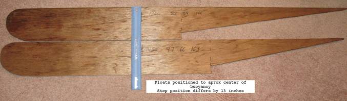
By using the C of B as the
primary guide rather than the step, the problem of the reduced heal flotation
would be addressed automatically but we would need to have the step at least
12” further aft and the question is would this affect rotation and lift off?
Clearly then, these floats
have different proportions to other Lotus floats and to floats from other
manufacturers so one would expect the manufacturer to provide some additional
guidance for rigging them on an airframe. The initial response from the
company, however, was that they should be mounted just like their other floats
with the step between 0 and 6” aft of the aircraft Cg. Given the smaller aft volume this can simply
not be the case. They must be moved further aft by some amount to compensate
for the reduced aft volume and prevent modest aft loads from sinking the float
and to take advantage of that more forward C of B for aft loaded aircraft..
One other possible issue is
that if the floats are mounted with the step in the same position as it was on
1260’s, the C of G of the float will be further forward and may complicate
weight and balance issues as well. With the early S7, the aircraft tends to
have a forward CG and mounting floats whose cg is more forward could be a concern.
I wanted to talk to people
who have actually installed and flown this float after using a 1260 to see how
they have dealt with the aft flotation issue and the step position. The owner
of Full Lotus, Jeff Holomis, refused to provide such references nor would he
comment on any research they have done on this issue except to point to some
YouTube videos which show airplanes taking off and landing. I suspect they may not have even thought
about it and certainly not done any real, substantial testing. All Jeff would
say is that there are many happy customers.
In 2009 I discovered that Ken
Smith had installed a set of 1450’s on a Rans S7 but it had not yet flown. He
said he moved the step back maybe 5” although this later proved to be not the
case. He did say a set is working OK on an S6.
Later that year I
was able to take measurements and fly the 1450 installation that Ken Smith made
up (a Rans S7 long tail with a 100hp Rotax). Frankly I was pleasantly
surprised.
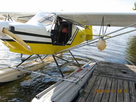
Turns out Ken had
not actually moved the floats further back but used his 51” step position as he
does for most of his installations which makes it easy to evaluate the company
suggestion of not changing the rigging from what 1260’s used. Here is a picture
of Ken’s setup:

The first test was
to put a person in the rear seat and stand on the float beside him. As
expected, the heels of the floats submerged illustrating that there was not
enough aft flotation..
While overall
take-off and landing characteristics were quite good, the owner did feel that
the fuselage should go further forward which should improve the climb up onto
the step. My feeling is that the fuselage should move forward at least 6” so
that the step is at 57” aft of the
firewall and 6” aft of the most rearward CG of 51”. On the other hand, the overall performance
where it is, is quite acceptable with one or two people onboard. If you look at
the videos you will see that the flotation is noticeably better than the 1260’s
without the look of much bulkier floats (as you would expect since the forward
barrel size is the same cross section).
You can see some
video of this aircraft on my pictures
page.
Ken’s rigging looks
quite professionally made and his choice of square tube spreaders with some
added streamlining works very well. Ken puts his spreaders closer (45”) than
most people do (55” to 63”) and he mounts the rear spreader closer to the step
than most people do (usually the step is about ½ way between the spreaders).
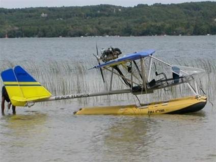
2008 Rans S7 Long Tail built by Brian Sandercock in Kenora
With the fuselage
6” further forward, the forward rake of the struts would not be so pronounced
(if the shift were done via the rigging and not just by sliding the floats on
the existing rigging). Ken also has used a narrower float width than I prefer;
his are at 66” whereas 72 to 75 is more typical. All of his rigging was well done including
the water rudder set up and stainless fitting in the floor for the rudder pull
up cable.
Finally, here is
one comment on the choice of angle between the floats and the fuselage where
the typical measurement is 3 degrees. I went to over 4 on the S7S above while
this set of 1450’s is at less than 2 degrees and they fly off and land just
fine. My conclusion is that trying for 3 is still a good approach but a little
deviation won’t likely hurt at all.
Update 2009/06/19
Just heard that
the owner has moved the floats aft 6”.
He reports that handling is much better; climb up onto the step has
improved and flat touch downs require some (normal) back stick rather than
forward stick which is common with Lotus floats to stop proposing. The
re-positioning was accomplished by sliding the floats back under the existing
rigging. This will put the rear spreader almost right at the step. On 1260’s
this would result in considerable flex of the aft portion of the float but
perhaps the third stiffener tube and shorter tail section on the 1450’s
counteracts the flex.
So, my
conclusions are that the 1450 is quite an acceptable choice (and much better
than 1260’s for the heavier S7S) but should be mounted at least 6” aft of
1260’s or other floats with a more typical step position.
Here is another
full shot of Brian’s very pretty S7:
Click for:
More info on
float sizing
Spent some time looking at
the setup of this pretty Baby Ace on Zenair floats.
During a recent rebuild, the
owner made several rigging changes to both floats and airframe. The floats are
now sitting at only 4* between float and wing centreline and the step is a full
6” aft of the aft cg. With these variations it will be interesting to see how
it performs (although it seems to be more in line with the German thinking).
Info on rigging design. Spreadsheet for predicting
take-off time.
C/G anomalies on the Rans S7.
The S7 fuselage was
lengthened in 2001 and called the S7S. There is no change in the airfoil or forward
geometry. As mentioned above, the CG range for the early models was 74 to 81”
aft of the prop hub.
For the S model, Rans changed
the datum line for CG calcs to be the firewall. The range for the S model is 46
to 50.25” aft of the firewall. For some
time I assumed that both aircraft had roughly the same CG range and aft limit
but a close look at the numbers shows this is far from true.
First Rans has narrowed the
range from 7” on the short tails to only 4 ¼ on the long tail. Next by
subtracting the 26” distance from hub to firewall, the converted range on the
short tail is 48 to 54”. The S model has had some FAA involvement.
I’m no engineer but maybe it
makes sense that if we have increased elevator authority due to the longer tail
we could tolerate the more forward 46” cg.
But why does the later model have a restricted rear CG position by
almost 4”? Should short tail owners learn something from this???