THERMOSTATS AND CABIN HEAT
RANS S-7
2013/01/08

Topics:
Keeping the coolant hot
Why Bypass vs Restriction Thermostats(ThermoBob)
Recent Earl’s
Heater in 2000 S7
Manual rad bypass
valve (Milloway)
Keeping
the oil hot:
Thermostasis better than
a Permacool
The problem
While capturing muffler heat
is an option on the S7, a more effective approach is to use engine coolant
through a small rad in the cabin. Some people have packaged small oil cooler
size rads hooked in parallel with the main rad but more than one person has
said it is inadequate. Perhaps by looking at the factors which affect heat
transfer we could make it work better.
The amount of heat we can get
from the rad is proportional to the difference between the coolant temp and
ambient temp so it is important to keep coolant temp high. One approach is to
block off the cold air flow to the rad with duct tape or a moveable shutter;
another is to restrict the coolant flow to the rad with a manual valve; another
is by installing a thermostat.
There is no doubt in my mind that
a full bypass thermostat is a necessity. They work flawlessly and consistently
with no monitoring and maintain temps right where we want them. For me, it is safer to take the risk of a
failed thermostat (something I have NEVER experienced) over a manual control
that I might forget to monitor.
Oil thermostats also help but, in terms of
cabin heat, are not as critical.
Keeping Coolant at
the right temperature:
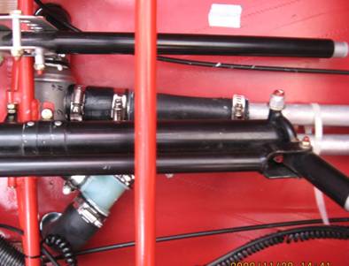
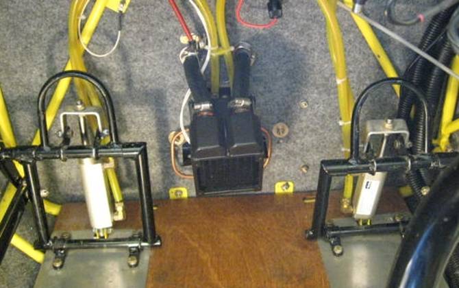
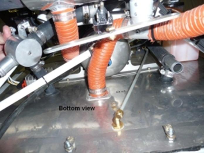
In one experiment, I installed
a Permacool thermostat (normally used in the oil system) in the coolant lines
to speed warm-up and maintain the right temp. Here is a picture of the lines
going to and from the rad on the floor between front and rear seats and the
thermostat (rad on the left, engine on the right):
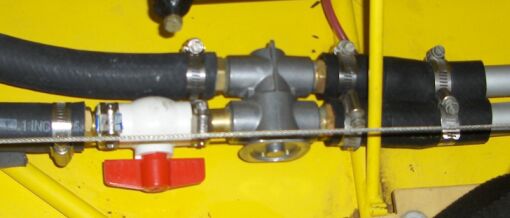
Caution. While the Permacool works very well in this
application in the winter, because its fittings are max ½” pipe, it will
restrict the flow of coolant which will likely cause
overheating during hot summer operation. There may be enough material to allow
boring it out to take 1” tubing but I have not tried this. Also for summer use
the seat would have to be machined as mentioned below.
See below for better solutions using full bypass thermostats.
Restriction vs Bypass
Thermostats
There are several methods
that incorporate a thermostat to control temperatures. The oil thermostat units
mentioned above, bypass the radiator by simply
offering a shorter path through the movement of one valve. The alternative path
through the cooler is still open so some of the liquid may still take it but
most will take the easier route.
Another method when flow
restriction is an option (it is not an option with oil) is to just close off
the flow leaving only a small aperture for minimal circulation, or close it off
totally and include a small diameter bypass route. Both of these methods cause greatly reduced
circulation through the engine when cold which could result in hot spots and
the second, with the permanent bypass, results in not all the coolant going
through the radiator when hot which reduces cooling capacity. This last point
could be quite significant on a hot summer day when maximum cooling is
required.
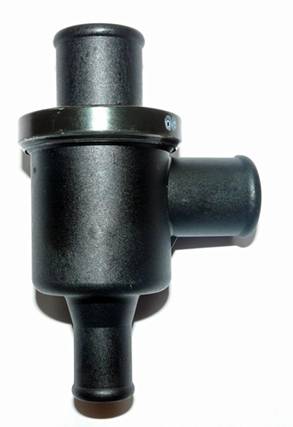
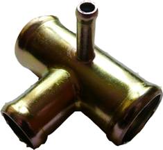
This unit (Thermo Bob) fully
closes the flow to the radiator but has a permanent bypass 3/8” hose to allow
some circulation needed to get some sensing heat over the thermostat.
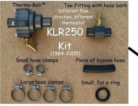
It appears to be a very well
made yet inexpensive unit which will provide fast warm up and temp control. Its
downside is that the 3/8” bypass is always open which will allow about 14% of
the flow to bypass the radiator. This will not be a problem in the winter but
in summer, when we need all the cooling capacity we have, higher operating
temps are likely. One good feature of
this unit is that it will fit 1” hoses unlike the two bypass units shown below,
is compact and may be the easiest to adapt to our plumbing.
At least one person has
experienced inadequate flow while heating up with this unit. The bypass
fittings might handle drilling to a large size but that would further
complicate the hot weather issues mentioned.
Since full bypass thermostats do not have these shortcomings, they are a
better choice.
Full Bypass
Thermostats
A better alternative is a
full bypass thermostat which is a dual valve system which results in both full
flow through the engine when cold or hot and zero flow through the rad when cold
for fastest warm up time. Here is a diagram which illustrates how they
work: (thanks to the Conair site for
this. They sell a bypass thermostat and the T needed.)
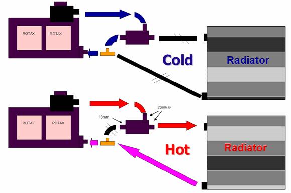
Note that these thermostats will work equally well
with the coolant coming from the engine entering the left side of the unit. In
other words the flow could be reversed with the hot coolant from the engine
going to the yellow T and the return to the pump out the top fitting.
To understand what
you are doing when you install one, think of the thermostat as a big “T”
fitting that you are installing on the line to the rad as well as a smaller “T”
in the line from the rad to the pump. The hose connecting the two “T”s is the
bypass. The bypass line can be much less
than 1” but doesn’t have to be as with the BMW installation shown below. The heater connections involve two more
“T”s, one in each of the two main lines, with the cabin heat rad between
them. In the examples below you can see
the heater “T”s combined with the bypass “T”s and, infact, the Motorad unit has
a heater port built in.
There are two of these units
from the automotive area which are worth looking at and one from the motorcycle
environment.
BMW
This unit, available from
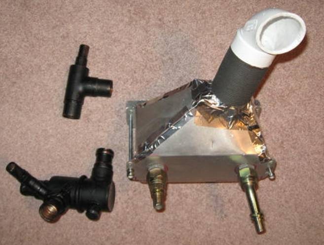
Here is one about to be
installed under the seat in an S7 with the under belly rad.
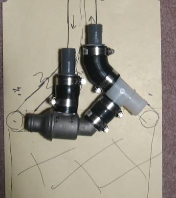
The
markings on the cardboard show the two tubes which carry the coolant to and
from the rad. The cross hatching is the rad with the inlet and outlet shown as
two circles. The housing has two valves in it which move together near the
"H" and "C" marked on the housing. When cold they are to
the left so the coolant coming in on the top left pipe is routed to the T on
the right and back to the engine bypassing the rad. When hot they are to the
right forcing the coolant out the left side, into the rad and back out to the
engine.
The
fact that the housing is for 1 ¼” hose actually works out fine at the rad since
the rad fittings are 1 ¼” (Rans has welded a 90 degree fitting on the 1”
aluminum tubes to increase size to the 1 ¼ rad fittings. These are no longer
needed with the BMW but reduction is need further along).
I bought a preformed hose at the auto
parts store to get the two 90's that connect the thermostat to the radiator
(not shown here) and the 45. The aluminum lines have to be shortened and a bead
put on them (or, better, get some new pipe and keep the originals in tact;
you’ll need two 2’ lengths if you take hose out through the firewall as I
did). (You could also put ½” Ts in these lines to hook up to a cabin
heater rad). The T and reducing fittings could also be welded up in aluminum.
Here
it is tucked under the pilot seat on a 94 S7 (rad to the left; engine to the
right):
And
here is a pic of the hoses exiting the firewall with a baffle to insulate them
from the exhaust stack heat:
This setup worked very well
winter and summer.
Here is another BMW stat
installed with a cabin heater in an S6 (Nati Niv Illinois) Nati points out that 1” copper pipe fits our
1” hoses while the 1” fittings that the pipe solder into fit 1 ¼” hose. The
fittings on the S6 rad are 1 ¼”.
The rad is top right; thermostat centre right; 1”
copper T on line from accumulator tank to centre port of thermostat. Also there
is the ½” hose to the cabin heater and temp or pressure port. Hidden is the T
on the right side of the thermostat going to rad and engine pump. Nati points
out that 1” copper pipe fits 1” hose while the 1” copper fitting fits 1 ¼ hose.
Here is another tidy S6
installation by Duane Zollinger:
And here is another one in a
96 S7 with a heater just forward:
The heater “T”s are just ahead of the thermostat (below that brass fitting which
has a bleed valve in it). These “T”s also reduce the 1 ¼ to 1” going forward to
engine.
Link to installation instructions with more pictures.
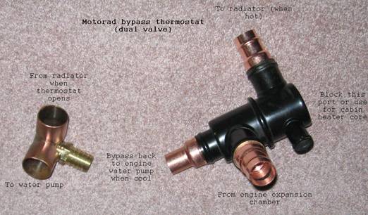
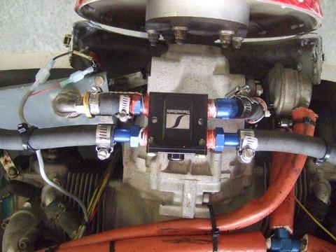
Motorad bypass thermostat.
This
unit works internally exactly like the BMW but has a more useful geometry in
some installations.
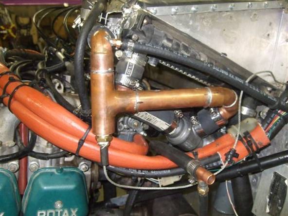
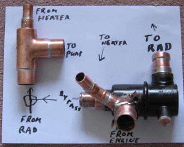
Here
is one version of the Motorad thermostat and copper/brass elbow/T to complete the
bypass circuit: There is also another
version with slightly different geometry and no fourth pipe. Here is a picture before the heater fittings
were added.
This
type of thermostat has
versions made out of both aluminum and brass. This one above is made out of
brass so goes well with copper pipe fittings. The two on the right are ¾ copper
x ¾ female pipe and had to be machined to fit the 1 ¼
thermostat pipes (as did the bypass fitting which uses ¾ hose).
There
is no need to retain the full 1” diameter on the bypass circuit because we only
need enough flow to prevent hot spots while the engine warms up. Here it uses
¾” hose; likely you could get by with ½” (when hot there is no circulation
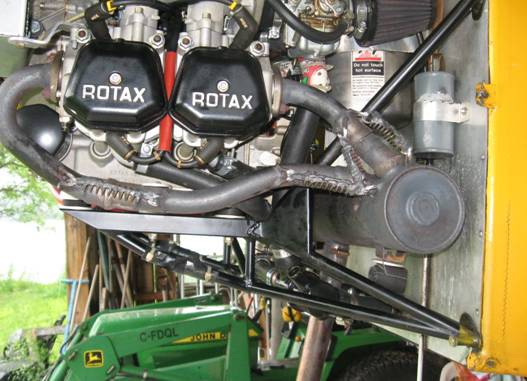
through this bypass).
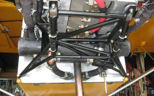
This
fits nicely within the motor mount on this 2000 S-7 short tail. Below is prior
to the installation:
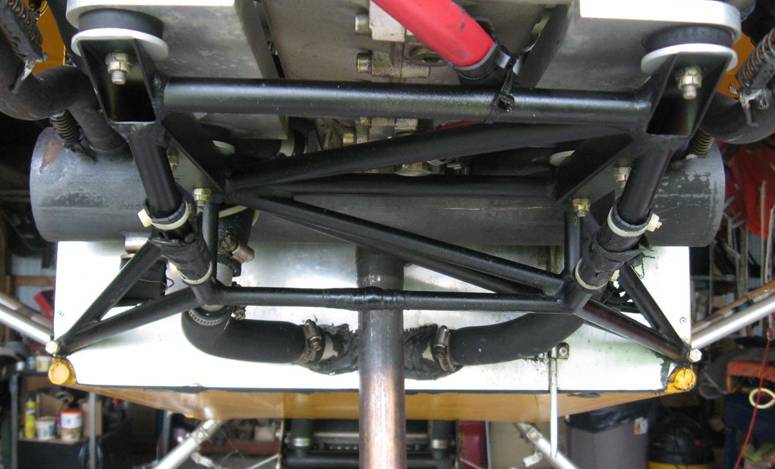
Here
it is installed (lower right of mount):
Below is the same unit
removed after 40 hours use to add the fitting for cabin heat.
The ½” fittings were added to the nipple getting coolant from the engine.
The right side ½” port was plugged
but next time I’ll use it for cabin heat. This arrangement has coolant from the
engine getting to the heater all the time unless a shutoff valve is in the
heater lines. (Thanks to Nati for stressing this)
The other copper T to merge
the bypassed coolant back to the pump is not present but drawn at bottom left.
See
pictures further down of the installed cabin heat rad. This setup has no
additional hoses or fittings in the cabin (just the rad bolted to the firewall)
and minimal additional plumbing in the engine compartment.
On
this installation, prior to installing the thermostat, it took 5 minutes for
the coolant temp to come up to the 140 degree mark. After installation it took
about a minute and was up to normal operating in 3 minutes (on a 26 C day)
Remember that the
unit shown above was made in brass so copper fittings worked well. More
commonly, they are made from cast aluminum so a different approach for the
fittings is needed.
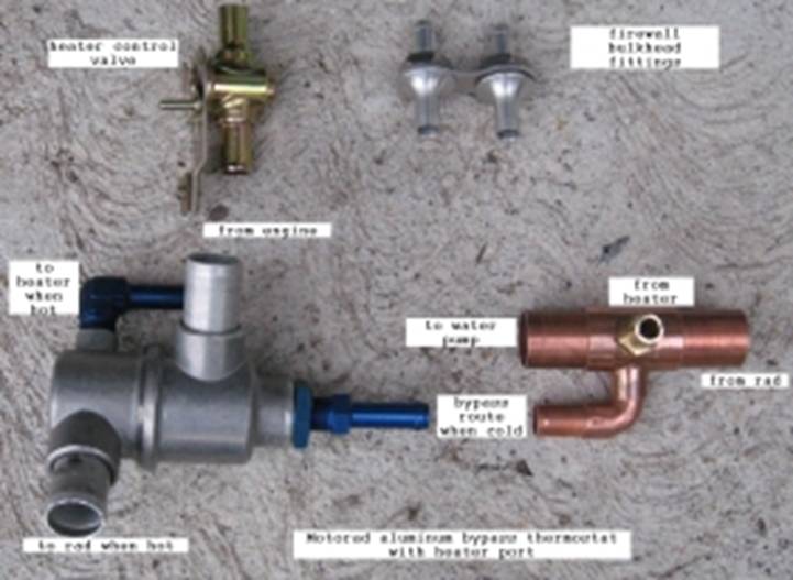
Below is an aluminum version modified to
use 1” aluminum tube with a ½” bypass. The original
ports were cut down some and the 1” tube has a bead inside for a snug fit.
Fittings will be fixed with JB Weld but could also be tig welded. The heater hose barbs
are threaded into the heater port on the thermostat and into the copper dual
“T”
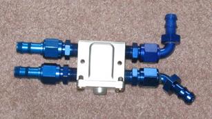
This one is going in an S7S
with a non stock rad position.
Here
is the final version shown with the heater. The thermostat housing now has both
the outlet to the heater (blue elbow, bottom right) and return from the heater
(blue elbow to right of orange bypass hose instead of the brass barb on the
copper fitting above). Line from engine to rad goes through 1” fittings on the
thermostat (In via bottom most 1” fitting and out top right 1” fitting) and
line from rad to pump goes through 1” black T fitting on left. The heater hoses go through the two bulkhead
fittings on the firewall.
The
1 ¼” thermostat outlets are reduced with 1” aluminum tube with a bead on both
ends, riveted and JB Welded to the housing. JB Weld withstands temps up to 500
F. The blue elbows are threaded into tapped holes. Because the heater is fan
operated, I’m not putting in the valve to control flow through the heater.
Also, because of the mostly upslope of the hoses, I’m not putting in an air
bleed valve.
Heater
hoses are ½”, bypass hose is 5/8”.
Because
of the location on the housing of the line to the heater, there will be no flow
through the heater when cold. There is flow to the heater (and to the main rad)
only when hot.
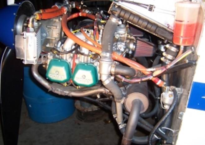
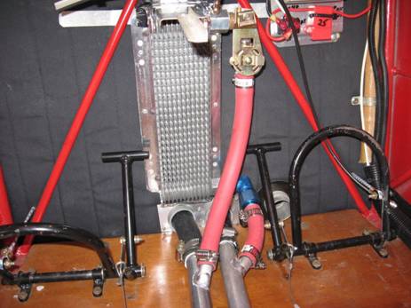
Here it is installed in a
1999 S-7S (with the coolant rad in a slightly non stock position):
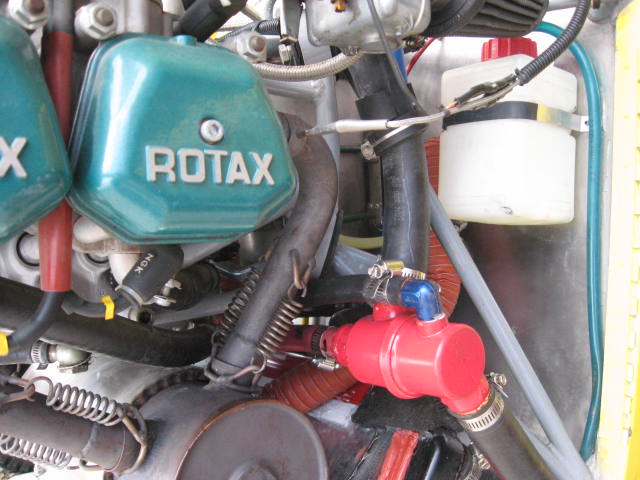
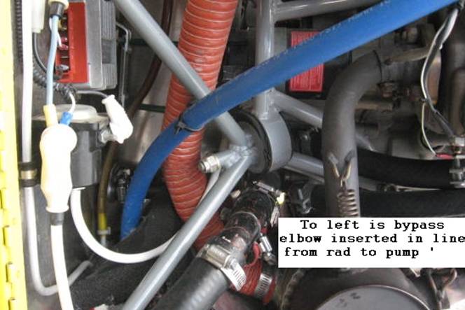
And here is right side with
bypass elbow in place:
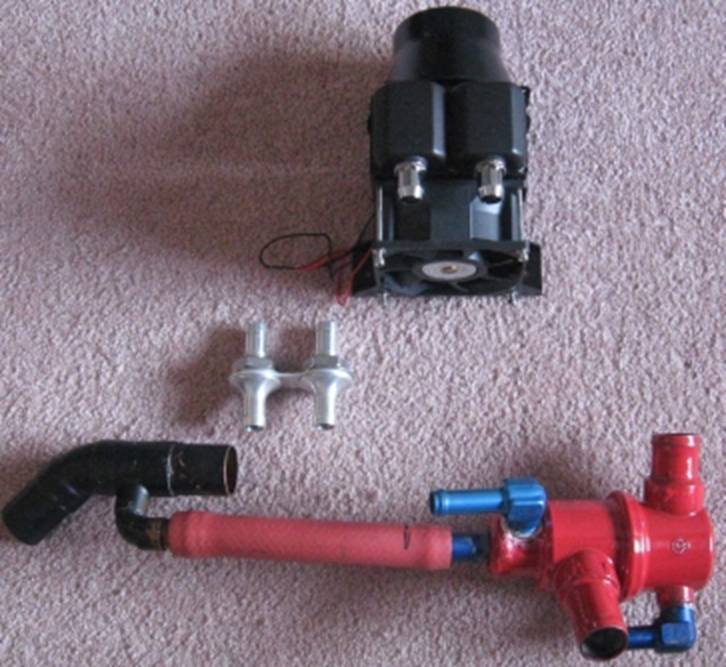
This is the small rad for
cabin heat:
Another full bypass dual valve thermostat:
This
unit offered by Conair in the
They also offer the
corresponding T fitting for the return line:
Note that this is a T
fitting but it is not 90 degrees for the 1” hoses as is the one shown above. If
that smallest barb were ½” it could be the heater connection
The net of it is
that geometry, space and adapting issues are very significant in your choice of
thermostat and none of the units out there drop in to every installation
without some adaptation and custom fittings.
With the thermostat installed
coolant temps will be constant in cold weather whether you are climbing at full
power or diving at idle; no shock cooling with a thermostat and no worries
about duct tape or monitoring a shutter.
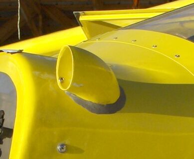
Air flow over the
rad
Another factor which will
affect cabin heat is the amount of air moved over the cabin heater rad. Because
the muffin fan doesn’t move a lot of air and re-circulates existing air, I have
used a supply of external air in some installations. I think this may also tend
to keep the moisture level down and be a safety factor. The slipstream air
enters a 2” central vac elbow and is routed to the rad through an automotive 2”
flexible aluminum hose to a shroud around the rad. Probably not everyone would
want to add such un-aerodynamic protrusion to their works of art. I tend to
like function ahead of form.
This is the rad with shroud:
If this unit
works well I may make a more elegant shroud out of fiberglass as well as
experiment with a shroud on the bottom (outlet) to route some heated air to the
passenger but the way it is seems to push some heated air under the seat
anyway.
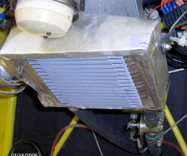
The coolant shut off valve is
at the bottom right. Shutting off the flow at the valve does not stop heat
transfer into the rad from the coolant so you are always getting some heat off
the rad. This is of some concern in summer
when you don’t need it.
First flight was on a -10 C
(about 15F) and cabin temp was quite comfortable. I’ll take some temp
measurements next time.
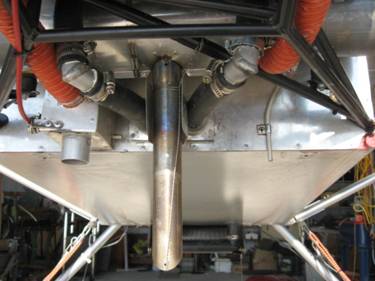
Another short tail installation:
Here is another heater
installation which taps into the cabin floor pipes to/from the rad in a 94
short tail:
At top right is the valve to shut off the flow and on
the hex fitting at the rad is an air valve to help with bleeding the air out
when filling the system and also to put some air in there when the heat isn’t
needed in the summer. Here is another view from the side.
And this is the central vac elbow that feeds it:
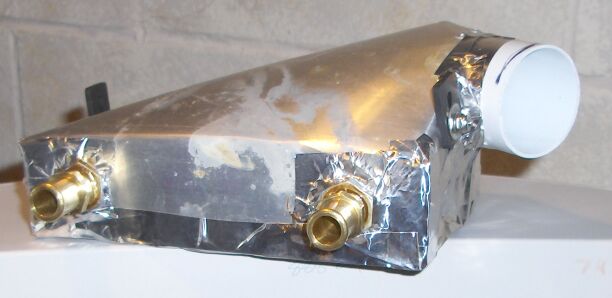
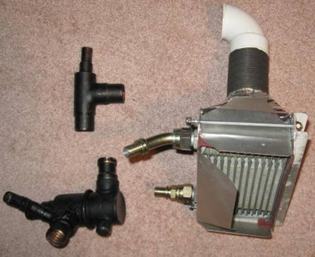
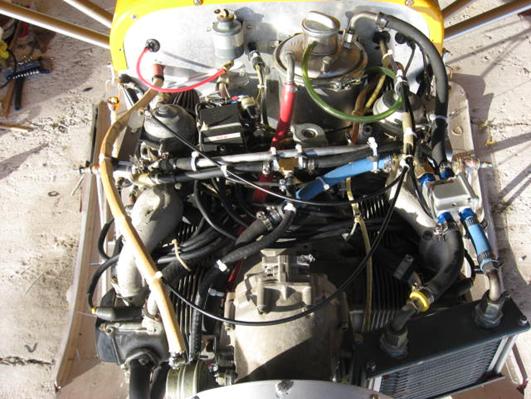
Recent “oil cooler” cabin heater in 2000 S7
Latest heater installation
for 2000 S7 short tail has the heater, an early S7 Earl’s oil cooler which
measures about 4 X 7”, mounted high on the inside of the firewall above pilot’s
right foot. The two through bolts tie it all together and hold it on the back
of the firewall. The pipe fittings fit through the firewall so no additional
coolant hoses in the cabin. In this location there is minimal additional hoses:
about 16” to feed the rad and a foot to get it back to the pump.
The rad, shroud and air supply pipe weigh 2.2 lbs; the
thermostat and T are another 1.8 lbs.
Those steel JIC fittings on the
rad are much heavier than more expensive aluminum and they cut the inside
diameter down to about 3/8”. This is one reason for going to the auto heater
style rads which have ½” copper pipes although overall these auto heaters are a
little heavier.
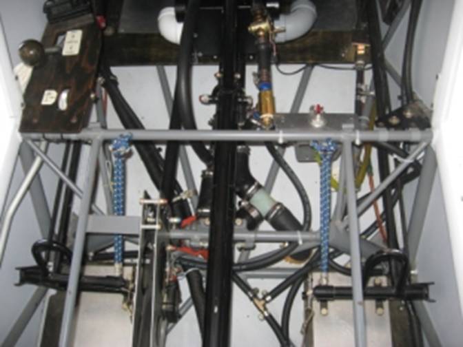
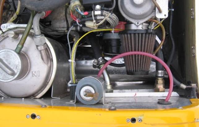
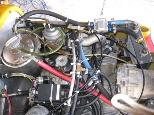
This is what the firewall
side of the installation looks like. The left fitting is a 45 elbow and the
hose drops down to the ½” outlet on the input side (hot from the coolant
expansion tank) of the thermostat; the right, straight hose barb connects to the T in the line from the main
rad to the pump. Moving the starter solenoid and regulator from this position
frees up a lot of space. That’s the ac
input to the regulator to the left of the brake fluid container.
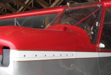
Many people successfully use
a small fan to move cabin air through the rad but I’ve found this 2” outside
source does a fine job. The first day I flew with it was about -5C yet the
cabin in front was 25C; too warm actually. I had to keep a cabin vent full on
(there is no coolant shutoff valve yet). The air inlet elbow is black on the
right side of the boot cowl in the picture below.
Manual control
If you do prefer manual
control, you may want to look into a control valve built by Joel Milloway. With
his system, he makes the heater the bypass circuit and controls how much flow
goes to the heater with a 3 way valve. It is an ingenious idea but will require
careful monitoring. The result is the same as with a thermostat except you
control the flow.
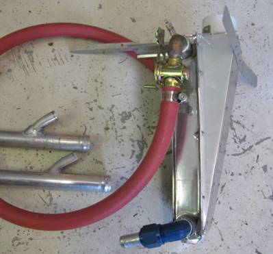
Here is a picture of an
installation with the T and the valve positions interchanged:
That’s the valve on the left
connected to the engine coolant pump at the top. This is an S-7S installation
with the rad within the cowl. On the right is the “T” in the line from the
engine to the rad (not shown). The hoses through the firewall go to the heater
inside.
Joel’s site is: http://millowaycomposites.com/
Oil Thermostats and
keeping the oil hot:
An oil thermostat like the
Permacool unit that Lockwood sells does a fine job of keeping oil temp constant
IN COOL air temps. With no cover over
the inlet to the oil cooler it will peg the temp at the thermostat rating in
all but the coldest weather.
The Permacool thermostats work
very well during the cooler months and do an excellent job of keeping the oil
temp constant in cold weather but appear to restrict cooling when we really
need it in very high ambient temps due to not fully closing the bypass circuit
allowing some hot oil to avoid the cooler.
These thermostats operate a
little differently from the way an automobile coolant thermostat works. In a
car, when the system is cold, the thermostat restricts the flow of coolant and
only allows full flow when the coolant warms up or it is a dual valve bypass
thermostat like the ones described above.
In the Permacool thermostat, when the oil is cold, a valve is open which
allows the full oil flow to avoid going through the oil cooler; as the oil
heats up this valve closes forcing the oil to go through the cooler.
If you open one up you can
see notches in the circumference where the large washer closes the flow of oil
across the unit (the valve) which it does when hot to force the oil to go via
the cooler. These notches allow about 10% of the oil flow to avoid or bypass
the cooler which is not what we want. The unit can be machined to remove most
of the notches thereby making ALL the oil go through the cooler. This was confirmed in a test by a guy in BC.
Further down are pictures of
this unit and details on the modification.
Some data:
The unit is shipped with a 77
C (171F)pellet (or “waxstat) so unless you change it that is the highest temp
you will see IN COLD weather when the thermostat is limiting temp and this is
too low for oil.
Most (if not all) automobile
thermostats have a pellet that fits the Permcool so you can select whatever
temp you want for any car at an auto parts store. You will have to carefully
remove a ring pressed on to the pellet which is not used when in the Permacool.
The highest temp you can find is maybe 195 F which is fine.
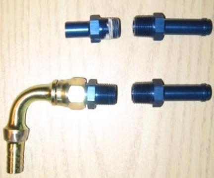
Lockwood ships units with ½”
pipe thread openings and fittings to fit. The racing shops sell both ½ and 3/8”
pipe thread. 3/8” is more than enough for the oil lines since the ID is about
7/16” like existing lines. Smaller fittings are lighter and take less space or
you can go to aluminum fittings from the racing shops. The ½” pipe models work
fine to control coolant flow in the winter. You would order 3/8”MIP x ½” hose
fittings which are readily available. Three straight and one 90 work well on an
S7.
Permacool Internals
Below is a picture of a pellet (wax stat) from
the Permacool.
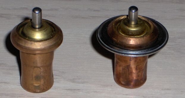
The pellet on the left is
from the Permacool; the one on the right from an automotive thermostat. When
installed the one on the left has a large stainless washer similar to the
formed ring around the one on the right. The size of the ring is almost the
same as the washer and could probably be used but to be certain, the ring on
the right can be removed and the same washer used. I have replaced the 171
degree pellet with the one on the right which is 195 for oil (for coolant I’m
using 180).
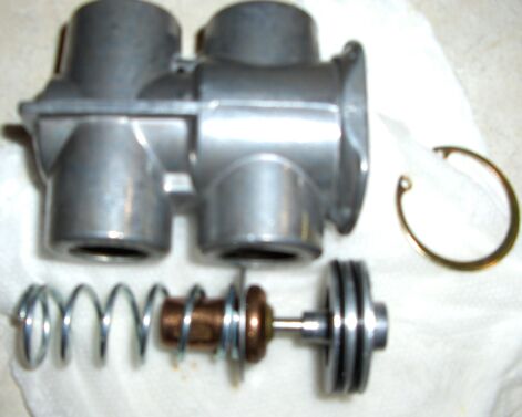
Changing the thermostat
“pellet” is quite straight forward. Removing the retaining ring allows the
piston to slide out followed by the pellet.
NOTE re oil temps
when using the Permacool thermostat.
This unit does an excellent job of maintaining
a constant oil temperature and thus is very slick for winter operation. There
is a problem during operation at 30 deg C OAT however in that the design of the
bypass is such that even when the bypass is closed when we want all oil to go
through the cooler it is not a perfect seal and allows some oil to bypass the
cooler raising temps by maybe 10 C or so. This can be fixed with some machining
of the seat. Below is a view of the seat which has been machined. You can see
that two of the four notches have been removed; parts of the other two are
still visible.
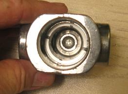
Since about .1” has been removed, I inserted a similar length
into the pellet pin socket to move the pellet that much closer to the seat. I
also cut one coil off the spring.
Thermostasis
thermostat
This unit is fairly new on
the market and appears to have removed or reduced a couple of the issues with
the Permacool. Here is a picture of one with some aluminum fittings added (it
does not come with the hose barbs).
Physically it is a little
smaller than the Permacool and in a more elegant package. Functionally it is
the same as the Permacool except it is available in a variety of temperature
settings up to 205 F so no exchanging of the wax stat is needed and it allows a
much smaller amount (2%) of the oil to bypass the cooler when hot so internal
modification should not be required. Not everyone agrees with this conclusion.
Some believe there is still a reduction in hot weather cooling.
The price is over double the
Permacool but it may be worth it. Here
it is mounted in an S7 (middle right side):
The fittings are 3 straight aluminum AN840-8D 3/8”
pipe X ½”hose and one JIC to pipe
(816-8D) and a steel JIC to hose. The three hose barbs were cut down like the
one on the top left.
This is a
205 degree unit and seems to be working quite well. The thermostat keeps the temp constant through variations in
power setting and OAT. Because the oil is bypassing the cooler when cold,
warm-up will be a little faster but not as dramatic a change as with the bypass
thermostat on the coolant.
Here is a similar unit
mounted in an S6:
Three straight barbs and one 45 (all with ridges
removed) make a clean installation on Nati’s S6. This location also works on
the S7 with either early or late cowl.
For oil cooler mods click
here