Modifications to
RANS S7 (AND S6) FUEL SYSTEMS
With a Rotax 912
2010/02/01
Back to Rans Topics
Certainly there are lots of these planes flying quite
satisfactorily with the stock fuel system components and layout so clearly
there is no urgent requirement to modify anything. If, however, you have needs
like mine (or you just can’t leave things alone), you may want to think about
some alternatives.
In the following material we will look at a modification
that provides for selection of fuel from the
right or left tank only as well as a mod the
eliminates hot starting problems
in the earlier, non bleed fuel systems.
The Rans system:
The early models have
a fuel system that looks approximately like this:
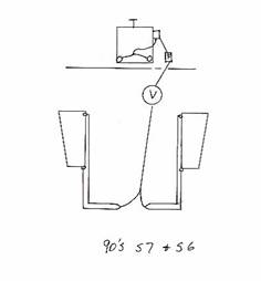
The key elements are:
Two tanks with front and
rear outlets.
Both outlets
for one tank go to the rear where they are “Y”d together.
The now single lines
from each tank are “Y”d to one line.
This single line goes to a drain and
sediment bowl down low
before it goes forward through a shutoff valve to the firewall
and up to the fuel pump inlet. Usually there is a filter in this line.
The output of the pump is “T”’d to feed
each carb.
Fuel lines were typically ¼” plastic (then
upgraded to rubber).
Some of the
characteristics of this system are:
Questionable
routing for conditions of low fuel and steep decent (especially if the “Y”s are installed high in the wing root)
Inadequate
filtering by today’s standards
Adequate but
not overly large diameter lines
Limited
backup in case of engine driven fuel pump failure
Inability to
select left or right side only
A pressure
build up in the line from the pump to the carbs which can cause re-start
problems due to fuel boiling.
On the plus
side, this is a simple system that works well for the most part.
Hot
Start problem.
Because there is a
check valve in the engine driven mechanical pump, fuel cannot flow back to the
tanks. This becomes an issue in the first ½ hour or so after shutdown. Without
air flow through the cowl, the temperature rises and causes fuel in the line
from the pump to the carbs to heat up and boil forcing fuel into the carbs
resulting in hard starting. To avoid this there needs to be a path the fuel can
take back to the tanks. The bleed line on the S7S installation accomplishes
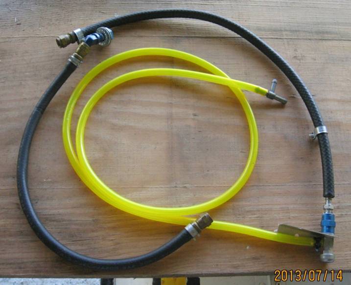
this (see below). Earlier installations with just the T fitting need to have a
bleed added. In the picture below there is an example of a bleed that goes
through the firewall and back up to a T fitting at the top of a sight gauge. To
be able to watch what is actually happening this line is partly transparent and
includes a valve to shut off the bleed to simulate the unmodified system. With
the valve shut off, in 20 minutes after shut down a huge quantity of bubbles
and fuel will flow when the valve is opened. By leaving the valve open after
shutdown the whole problem is resolved.
S7S Updates:
With the S7S model,
Rans addressed the first point on routing by taking the forward tank outlets
forward and down the door post to join up with the rear lines under the front
seat.
Also on the S model
Rans installed a traditional style gascolator on the firewall to improve on the
filtering issue. Some argue that the gascolator is an 80 year old design which
does not provide the filtering capability of modern filters like the ones used
in marine applications. It can also be argued that its placement is not optimal
due to poor accessibility and heat.
The S model now uses
3/8” (for the most part but at several points the size is less than ¼”)
aluminum lines. For example, while all
of the aluminum tube is 3/8”, the front tank outlets are ¼” fittings. My
understanding is that with the ¼” orifice, there is no improvement in fuel flow
by feeding in to 3/8” tube.
To provide backup
there is an electric fuel pump also on the firewall.
This is what the S7S
fuel system looks like.
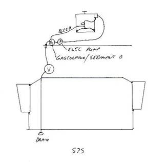
One other change in
this system on the S7S is the fuel splitter manifold for distributing the pump
output to each carb rather than just a “T”. The manifold adds a port for a fuel
pressure sensor and a bleed port to enable some fuel circulation back to the
gascolator, which some say is related to “vapour lock”.
Why change?
While feeding from
both tanks is certainly the simplest approach which satisfies most people’s
requirements, it does not meet mine. Being able to feed from one side ensures
maximum fuel usage (and less stress) in an emergency situation by being able to
drain one tank. Another benefit for aircraft that have engines that need high
octane fuel is the ability to put lower octane in one tank for use in lower
power cruise while keeping some high octane in the other for takeoff. This is
important to me while float flying where I can take on lower octane marina gas
when premium is not available. At cruise power, regular car gas is quite
adequate even in a 912S engine. I grant that there is a risk doing this should
I mistakenly take off on the low octane tank.
I question that
simply adding the electric fuel pump in series with the mechanical is the only
or best solution for backup of the engine driven pump.
There are hundreds of
high wing aircraft that use only a gravity feed system with no pumps of any
kind. I acknowledge that the higher location of the Rotax carbs is not as
optimal as the under engine carbs on Lycomings and Continentals but my tests on
the S7 show that gravity feed will work but only if the restriction caused by a
non operating mechanical pump is bypassed.
Fuel flow through a non functioning mechanical pump is about 20 L per
hour which is adequate for level flight but not for full power, so, by-passing
it while using gravity feed is essential.
I am also concerned
that there could be a failure of the mechanical pump which could result in a
blockage that would restrict the flow produced by the electric pump even more,
so my feeling is that the electric pump as backup is not the best nor simplest solution.
An Alternative
Here is a drawing of
what I am putting into my S7S:
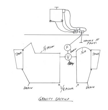
The main fuel
selector (V) is a
Filter (F) is a Racor with water
drain (I was going to keep the stock gascolator but not only is it outdated, it
has no decent mounting points).
The filter is under
pilot seat (easier
to get at and leaks detectable sooner).
This is a Racor
filter/water separator beside the stock gascolator:
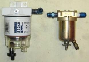
The Racor weighs 1.2 lbs vs the stock gascolator’s .4 lb
The firewall
mechanical pump bypass valve is a stock left/right valve. Flow is the reverse
of normal with fuel entering the usual outlet port and being directed either to
the mechanical pump or directly to the manifold (not the intake manifold, just
the pre-carb one) for gravity feed.
The new manifold is
made out of ¾ x 1” aluminum. It is
rigidly attached to selector valve and the unit bolted to the firewall.
Rear lines are
3/8”aluminum from tanks through selector valve and filter to manifold, ¼ to
carbs, 5/16 to mechanical pump. The
forward left line from the tank to the selector valve is the original 3/8”
(except for the ¼” section out of the tank); the right forward line is ¼” to
minimize bulk where it runs along side the feed to the firewall.
Yes there is a little
more tubing inside the cowl compared to the stock setup (the line from the
mechanical pump to the splitter manifold is about one foot longer to take it
back to the firewall and one line to the left carb is also maybe a foot longer)
but overall, line sizes are larger so the result should be better fuel flow.
Having the splitter
manifold bolted to the firewall may provide a heat sink which could help to
keep the fuel temperature down lower.
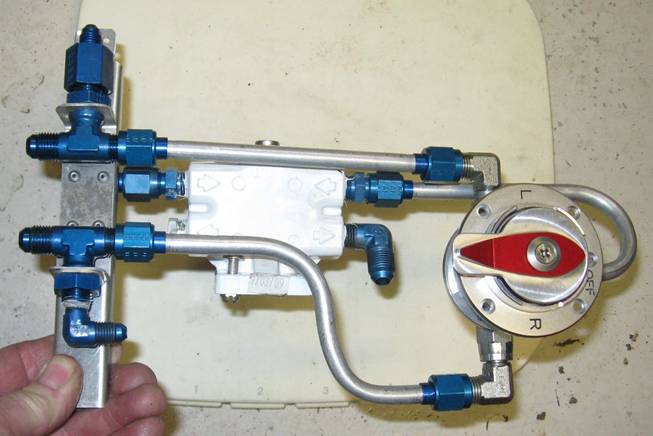
Here is the new
splitter manifold as it would sit on the firewall:
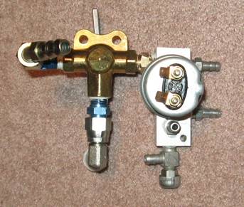
Fuel enters from the
bottom left through the firewall, then up to the brass valve. The top left
outlet, when selected, goes to engine driven pump. For gravity feed, the right
outlet is selected and fuel goes to the manifold block.
The two outlets on
the right go to the carbs;
the one above the drain valve is input from pump.
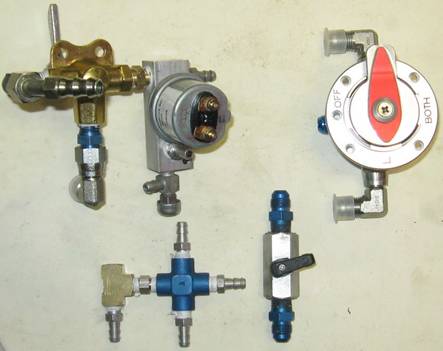
Below is the old and new
valve/manifold setup (I’ve dropped the pressure sender and gauge as well).
Here is the guts of
the system as it will go under the front seat cross tube:
The rear tank lines
go to the T’s as do the front tank lines; the outlet from the filter goes to
the right side of the cabin and forward to the manifold on the firewall. This is the side view
and the rest of the parts added:
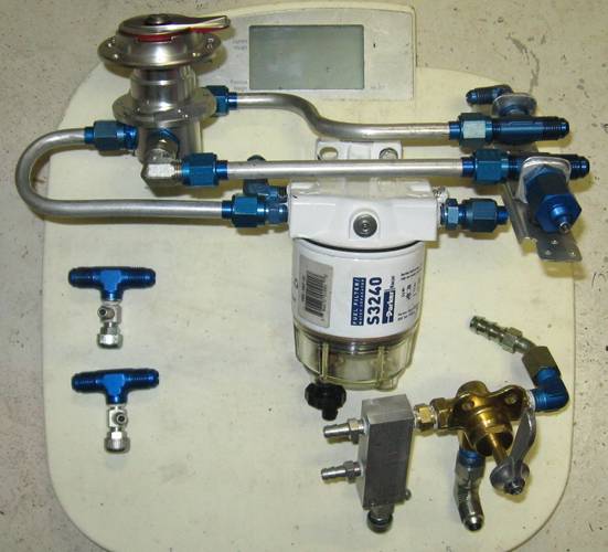
The filter allows for two pair of inlets and outlets. The pair on the
left is the set in use while the right side has the second outlet plugged and a
cap on the unused inlet to make it easier to add an aux tank later.
So, at first this
looks a little more complex than the existing system but in terms of parts
count, it is not.
The parts shown below
were removed from the stock system and weigh 4 lbs:
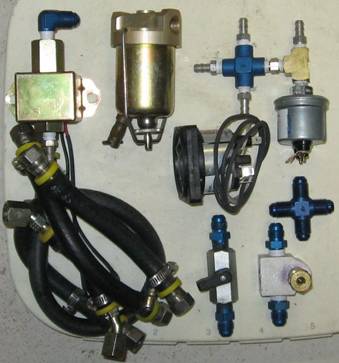
All those steel hose barb fittings and 3/8” rubber hose are heavier
than aluminum tube with aluminum nuts and fittings.
Here is the completed
valve/filter assembly:
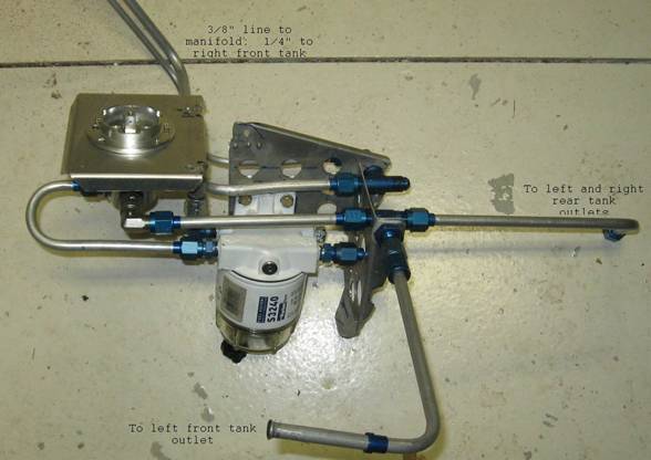
It turns out that the
total weight of the new system is also close to 4 lbs or about the same as the
old system. So, it is looking like the
result is a foolproof, gravity feed backup plus left/right selection with
better filtering and more accessibility with no weight penalty and it looks so
elegant!
It did take considerable time and bucks to put
it together though.
Update
Kimberly P. of Titan
fame pointed out to me that Rotax specs say the carbs require 2.2 psi fuel
pressure which would mean that gravity may not work since that pressure is
maybe 5’ of drop. A flow test on an actual carb gave total flow for two carbs
of 4.5 USG/hr or 17 l/hr. this would sustain a decent cruise power setting but
not a full power climb. I may have to put the electric back up pump in after
all.
Feel free to let me know
your thoughts on this. peterc@pipcom.com
I
have not yet flown this configuration nor checked the at rest gravity fuel
flow.
Return to Rans Topics page