Cooling a Rotax
912
in a Rans S-7
2013/04/07
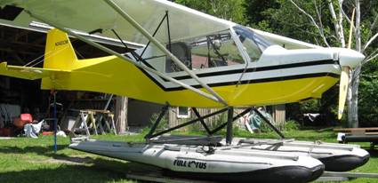
2004 S7S on 1260 Lotus
Topics include:
What does cooling a 912 entail?
How has Rans designed
the oil and coolant cooling systems over the years?
Reducing oil temp
with larger cooler
Reducing oil temp by
changing air flow over the cooler
Coolant radiator
evolution in the S7
Other improvements
in air flow
Background:
First, it is important to
keep in mind that there are many variations of the S-7 equipment depending on
the kit year and subsequent updates. Coolant rads started out under the pilot’s
seat when the 582 was the engine of
choice, then were moved backward a couple of feet under the passenger seat to
compensate for the 912 weight and then were mounted forward of the firewall on
the S model. Late 90’s models also have the rad under the pilot.
As with any engine, the Rotax
912 installation must be able to dissipate the heat produced. Because of its unique design with water
cooled heads and finned cylinders, the 912 gets rid of heat via air over the
fins, heat transferred to the coolant and to the oil as well as, of course,
through the exhaust.
For anyone seeing their first
912 installation in a Rans (and likely in many other aircraft), the first
noticeable difference from a certified aircraft with a Lycoming is the lack of
a pressure cooling setup where all the air entering the cowl inlets at the
front is forced to flow over the cylinders by baffles around the perimeter of
the engine which prevent incoming air from escaping around the sides, front or
back of the engine. In these aircraft, all the incoming air flows over the
cylinders or forced through an oil cooler, usually from the top down, and out
the aft bottom of the cowl. In a Rans,
air does enter at the front but is allowed to find any route it wants to get to
the exit. Some people feel that this
contributes to reduced need for carb heat because the carbs may be getting this
pre warmed air all the time.
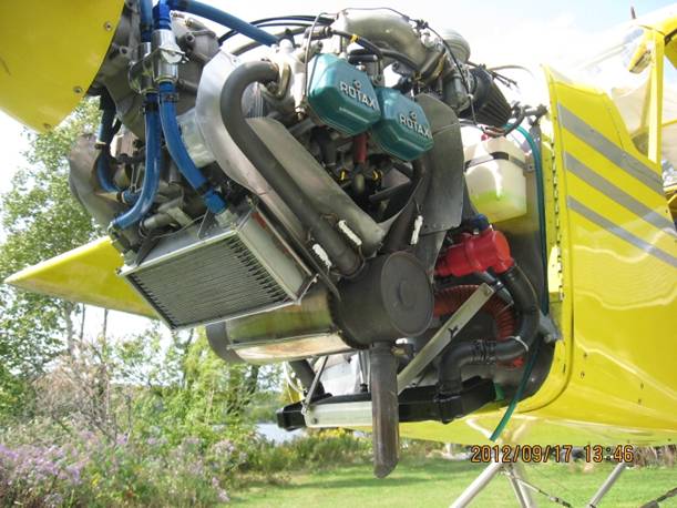
Some 912 installations do
have a form of pressurized setup by means of a fiberglass molded shroud on top
of the engine with an air inlet tube feeding it. This item can be seen on Rotax
parts diagrams. Others who wanted more direct airflow over the cylinders have
used scat tubing to route air there. An example of this method is shown later.
Based on the much smaller
cooling fin size on a 912 compared to a Lycoming, it is clear that the 912 has
less of its cooling requirement from the air over the cylinders. Thus the
undirected blast of air can be adequate.
Cooling the coolant and oil
does demand more finesse.
Keeping the oil
cool For
more discussion on keeping oil and coolant hot (thermostats), click here
Let’s look at oil cooling
first. Here is a picture of some oil coolers that have been installed in the
Rans S7:
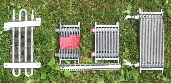
There is information on the Earl’s
(or Jegs Racing) site showing the heat transfer capabilities different cooler
designs and the Earls style like the 3 right hand ones are the best.
Oil coolers in the early 90’s
were the S tube type like the one on the left and were mounted horizontally
above the engine with no direct air hitting them. Because this type and
placement was quite ineffective, some people added a second one in series but
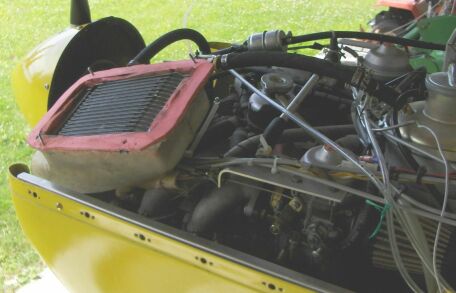
that also was inadequate. By the mid 90’s Rans was shipping an Earls style
cooler (like the one with the red tape on it in the picture, 13 rows) which is
one of the better designs, mounted vertically in the left air inlet
nostril. This was an improvement over
two of the “S” tube style but was barely adequate on an 80hp in high
temperature days. The 100hp engines required more and especially if operating
on floats with slower air speeds. Thus Rans began shipping the larger cooler
shown second from right above (same width but 16 rows).
Reducing oil temps:
Larger oil cooler
Most people with an early S7
who want to lower the oil temp will simply go to the larger cooler. This will
drop the temp by about 25F. The main
steel mounting bracket needs extensions as do the other 3 clamping rods and
outer S bracket. It will also sit closer to the exhaust pipe so a heat shield
baffle is important.
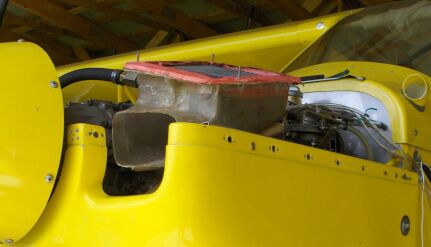
On this 94 S7 the oil cooler
developed a leak, probably because it was mounted without the encasing
brackets, so I replaced it with the larger one off the S7S:
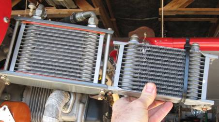
Rather than the AN3 bolts tapped
into the aluminum spacer tubes, I use larger tubes and 10/32 threaded rod right
through.
*
Does the S7 have
the optimal oil cooler position?
The stock oil cooler location
in the left nostril has several disadvantages:
1.
It prevents the
cooling air from hitting the cylinders directly like it does on the right side.
2.
Heated air from
the rad is allowed to enter the engine compartment.
3.
Putting a rad
perpendicular to the slip stream without any ducting is inefficient.
4.
The back side of
any rad should be in an area of low pressure, not the high pressure created by
air entering the right nostril.
5.
The rad almost
touches the exhaust stack below it.
Mounting the oil
cooler under the engine:
Several of the above disadvantages
can be eliminated by mounting the cooler below the engine and feeding it air
trough a scoop. The bulkier cowl on the S-7S lends itself to this solution.
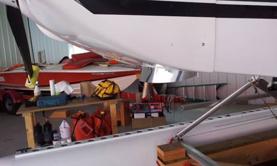
Below is the extra large rad shown above mounted under the 912.
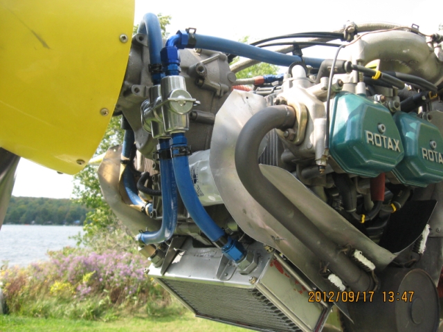
Notice the aluminum baffles
to keep exhaust pipe heat away from the oil cooler, hoses and the oil filter.
Also notice the use of constant tension hose clamps

That’s a Permacool thermostat in the oil lines with a
194F waxstat installed.
The 912 crankcase has four
8mm tapped holes on the bottom sides of the case. The front two are unused and
that’s where the forward mounts on the oil cooler attach. The rear two holes on
the S7-S are used for the motor mount so I added tabs to attach to the aft
mounts on the oil cooler. These aft mounts are basically ½” oil line hose about
5” long with a metal tube slipped on before flattening to bolt to the tabs.
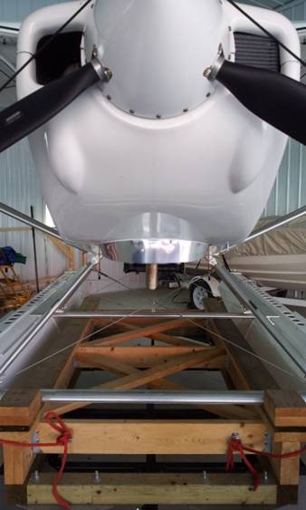
A small scoop feeds the oil cooler:
One radical mod:
Positioning the oil cooler
vertically in the air stream with no ducting is not optimal. A more elegant approach is to re-position the
rad and shroud it to force all the incoming air to go through the rad and route
the warmed air out of the cowl. To accomplish this I used a wood and foam male
mold to produce the fiberglass holder for the oil cooler with a small air
inlet. This is the smaller oil cooler used on early S7 short tails.
This shows the rad mounted in
the fiberglass duct with the cowl off:
With the cowls mounted and
the rad fastened down there is good clearance from the manifold and
throttle/choke cables.
Below is the front view:
Here is the finished cowl
with a louver above the oil cooler to help pull out the heated air.:
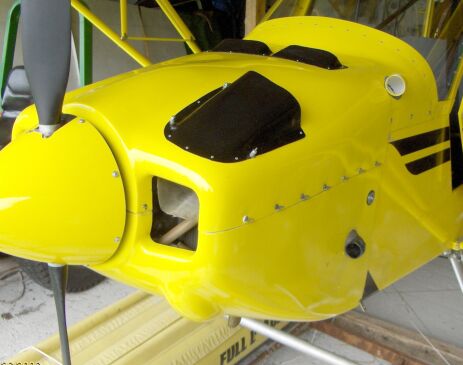
The duct occupies a little over
½ of the air inlet opening leaving a good blast of air for the cylinders.
This picture also shows a top
rear cowl exit louver which helps to reduce temps inside the cowl after shut
down.
Monitoring temps inside the
cowl showed a significant temperature increase after shutdown. The louver at
the top rear of the cowl allows this excess heat to flow out.
This position for the oil
cooler does create extra work to remove or replace the top cowl. Using ½ turn
fasteners instead of bolts would reduce this extra effort.
The smaller black scoop on
the side directs air over the muffler and the top yellow scoop provides air for
the cabin heater using the same size Earl’s as the oil cooler.
Before the changes and with
an oil and water thermostat, on a 30C+
(90F+) degree day, oil temps were 270 or so and water (cylinder probe)
215. Now without thermostats and with
the new set up, temps are 230 and 180. Probably ½ this benefit was due to
removing the thermostats (The Permacool thermostat has a problem in hot weather)
and the rest due to the changes.
Other factors
Ensuring that the air exits
easily from the cowl is quite important.
Rans used a shallow cowl air
exit flange (around the exhaust) on early S7 aircraft but most feel that
enlarging it (like on the S model below) increases air flow without enlarging
the inlet openings.
Coolant rad design
and placement or keeping the coolant cool
Just as with oil
cooling, the design of the coolant system has also evolved in the S-7 over the
years. The coolant rad started out under the belly like this:

Hoses from the engine connect to aluminum
tubes that run through the firewall, along the floor boards, then down to the
external rad. This placement is a good design with a small frontal area, angled
rad and an area of low pressure where the air exits the rad. This view
illustrates this a little better:
In fact, this
position reflects widely accepted theories on air flow over a radiator that go
back to the design of the cooling system on a P-51 Mustang. High speed air is fed into a relatively small
area scoop (compared to the area of the rad), is allowed to expand and slow
down before it goes through the fins of the rad and then exhausts in an area of
lower pressure.
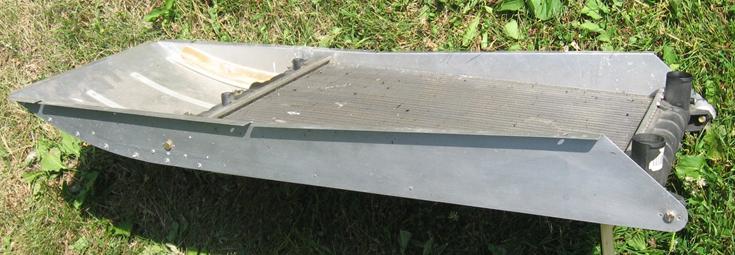
Here is an S-7
rad before it is bolted on the belly. Air enters in that section between the
rad pipes (about 20 sq “?), the area of the rad is about 235sq”. The nose down
slope helps to get the exit side of the rad out of the high pressure slip
stream thus creating an area of lower pressure for the heated air to enter.
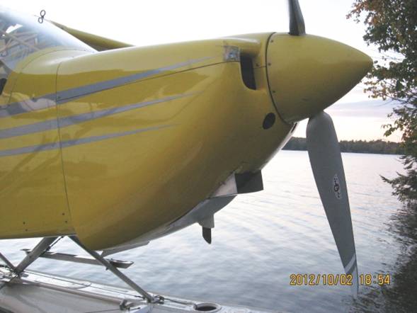
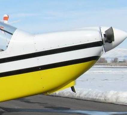
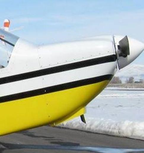
S-7S Design
Below is a 2004
S-7S. Notice there is no coolant rad visible.

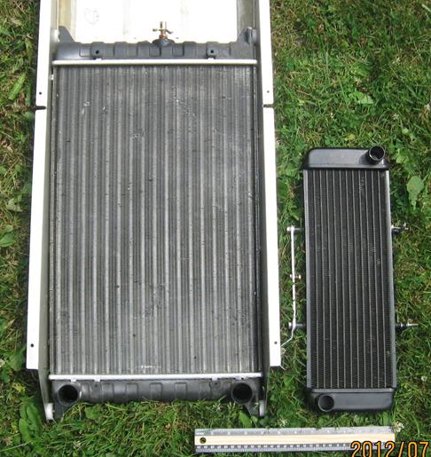
On the S model,
Rans dropped the belly rad and went to a smaller rad within the cowl shown on
the right below. The S-7 rad is about
237.5 square inches, while the S rad is only 67.5 square inches. The S-7 rad is tubular (34x ¼” id? tubes)
with all the coolant apparently going down one half of the rad (through 17
tubes) then coming back along the other half.
The S rad is a plate setup with each of the 11 plates having a cross
section area of about 1/16 x 3/4”. The 1” wide plates have two small
rectangular coolant paths that measure very aproximately 1/16” x 3/8” These two styles are also seen in oil
coolers.
This much smaller
rad is mounted horizontally just ahead of the firewall near the outlet air
path.
Here is a
comparison of flow area and surface area of tubes:
Surface area of
small rad: 11 plates at 1.25” x 2 sides
x 13.5” long = 371 sq”
Surface area of
larger rad: 34 tubes x diameter of aprox .33x 3.14 x length
of 19” = 669 sq”
Flow area of
small rad = 11
x .06 x .75 (all aproximate) = .5 sq”
Flow area of
large rad = 17 x .125 x .125 x 3.14 = .83
sq”
Interesting to
note that the cross sectional area of a 1” hose is .79 sq” so it would seem that the small rad
also restricts the flow.
These numbers
suggest that the larger rad should be much more effective yet it was not
overcooling any 912.
This smaller rad is
positioned close to the cowl air exit opening at the base of the firewall.
There is no additional baffling (on a stock S-7S) to force air through the rad
although some owners have added a baffle to prevent some air from escaping
between the rad and muffler. Frankly, I find it curious that this much smaller
rad, without the benefit of the direct slip stream air, is at all adequate,
however, in moderate temperatures, it does work.
In this modified cowl S model, the rad is
angled down so that the forward edge touches the bottom of the cowl to force
exiting air to go through the rad rather than around it:
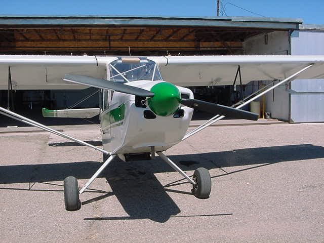
Another idea
Some people have found that
providing additional air entering the engine compartment contributes to overall
lower temps. The builder of one S-7 chose to leave off the large spinner and
its’ back plate to allow air to enter around the prop hub. Another builder advocates cutting two tennis
ball sized holes below the spinner like this:
On the other hand,
ensuring the cowl exit air is not constrained has proven useful in other
aircraft. The exit flange on the cowl above is really quite small and while
some have found modest increases don’t do much, here is an example of one that
dramatically reduced cylinder head and oil temps on an 80hp on floats. This
solution has a flange depth of 3”.
One builder
decided to make an even more dramatic change.
Here is an interesting look
at airflow mods on an Avid: http://avidflyer.wikia.com/wiki/912_Cooling which directs air right to the cylinders. It
started out with some different cooling issues than we have on the S7 however.
See details on cabin heat
and thermostats
Back to Cooling/Heating Topics page
Peter
*