Rans S-7 and S-7S with Rotax 912
Assembly topics
Last updated 2011/02/25
The material presented here
has been provided, for the most part, by Rans S-7 builders and owners. The
intention is to provide a useful supplement to the Rans documentation. This
material has NOT been edited by Rans personnel and in some cases may only
represent the opinion of the builder. Exercise normal caution and judgment
before accepting this material for your own use.
Most of the following
material is based on the S7S airframe. Much of it applies to earlier models as
well. If you are working on an earlier kit, make sure what you are reading
applies to it. Wherever possible we have tried to indicate if it is for the “S”
only or all models (A). Some general topics could also apply to other aircraft.
2007/03/03 General Assembly: text and pics (wing structure, aileron
bellcrank)
2007/03/13 Pre- S7S Topics
2008/11/29 Pulled rivet technique
2011/01/23 Panel, firewall access
2011/01/28 Wiring: diagrams and Master issues
Topics
1.
General assembly
instructions. (A)
2.
Landing gear
seating in socket
3.
Fitting
fiberglass boot cowl (S)
4.
Windshield (S)
5.
Panel and
firewall accessibility (pre S model)
6.
Wiring (A)
7.
Battery location (S)
8.
Ground connections (A)
9.
Propeller choices
10.
Cold weather
modifications (A)
11.
Lifting rings
11.
Pre S7S Topics
You will find a useful
reference document covering metal work, riveting and painting topics at:
http://www.pattersonaerosales.com/Misc/StandardPractices.pdf
This document covers aspects
of solid riveting as well but there are no solid rivets in Rans kits; only
pulled rivets. See below for some comments on dealing with pulled rivets
(contributed by Gordon in the
Bolts:
Different components and
materials require different assembly techniques. There is an excellent section
on the proper sizing and tightening of bolts in the above document. For example
a bolt holding the motor mount to the firewall needs to be torqued to a
specific value to achieve the correct strength. It is in tension and needs a
full sized “tensile
nut”. Bolts retaining many other parts, for instance the landing gear in its
socket are not in tension but in shear and so nuts can have fewer threads
(shear nuts) and need not be tightened to maximum torque values. Similarly
castle nuts with cotter pins usually indicate parts in shear and so do not need
to be torqued.
Concerns when
bolting aluminum
The wing has several aluminum
tubes bolted to U brackets on the spars. Here excessive tightening can distort
the tube and bracket and/or bottom the nuts on the unthreaded parts of the
bolts; both situations must be avoided. In the picture, the bolt has been over tightened deforming tube
and bracket and probably bottoming nut on unthreaded part of bolt:
Other joints such as the strut attach plate to
wing spar utilize internal tubes to prevent distortion allowing proper torque values
to be used.
Also in the above picture you
can see that one of the rivets in the clip has a dark ring around it indicating
it was not seated properly before pulling. In this case the head needed to be
filed to clear the adjoining clip.
Riveting
The “pulled” rivets used
throughout the Rans products are quite simple to use but still require correct
technique. The Murphy document covers
proper drilling and preparation of holes.
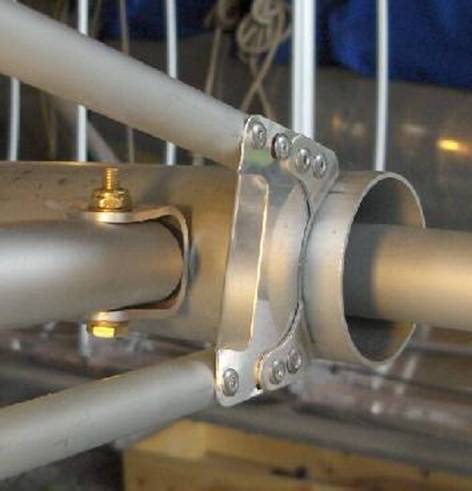
You must ensure that the two parts being riveted are mated tightly together.
This sometimes requires appropriate filing. For example the aileron bellcrank
is riveted to a spindle. The spindle is machined with a shoulder that prevents
the bellcrank from seating tightly to the spindle. You need to round or chamfer
the edge of the hole in the bellcrank to achieve proper mating or you will end
up with improperly set rivets. See
picture below:
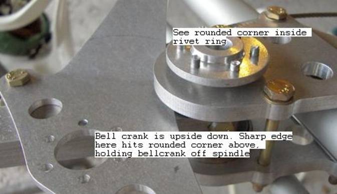
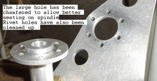
This is an S model bellcrank
but a similar problem existed on earlier models.
Tips for working with pulled
rivets
General aircraft sheet metal practice is to use the drill
diameter in
decimal rather than fraction. So 3/8" is .375", 1/8" is
.125" etc.
Fortunately there is not too much that can go wrong when setting pop
rivets if you have them square to the hole and the head in contact
with the materials being fastened together. It is good practice to
use the correct size clearance drill. These are identified in the
build manual by a number rather than a size, e.g. #11, #30. The
clearance drill ensures that the rivet can expand just the correct
amount during setting without buckling thin materials or over
stressing thicker materials. Deburring the hole is
important too as
any external burrs will hold the rivet head off the material and
result in a poor job.
The rivets should all look pretty much the same and if there big
differences then it could be that you are not drilling the holes
squarely with the material. A slightly elongated or oversize hole
will cause the rivet mandrel to pull further through the rivet and
break off outside the rivet head – much the same as using a rivet
that is too long for the material being fastened together. Sometimes
this happens anyway when the rivet size is not optimum, in this case
I carefully grind the exposed shank off with an air powered die
grinder if the rivet is somewhere the mandrel needs to be flush with
the head. A Dremel should work Ok but be very. very
careful not to
knock the mandrel head into the rivet as this part provides a large
percentage of the shear strength of the rivet.
If – and when – you need to drill out a badly formed rivet get a
small diameter pin punch, or use a discarded rivet mandrel from the
same size of rivet, and knock out the steel mandrel from the formed
rivet then drill the head off the rivet. Aim to simply drill the
head off the rivet then use a punch to knock the rivet tail out of
the hole. This helps keep the original hole size from
being
oversized and in turn giving a poor set on the new pop rivet that you
install. Don't deliberately drill all the way through knocking the
tail out with the drill bit, and don't try to drill the rivet out
with the mandrel in place as the drill will run off centre and spoil
the work piece.
Gordon
Windshield
The Lexan provided by Rans is
designed to provide a one piece windshield and sky light. Tipp City Plastics
can provide a formed plexiglass windshield which is easier to install and does
not have the Lexan characteristic of cracking when under bending stress and in
contact with gasoline. Installing this formed windshield requires a joint with
the skylight above the main spar carry through.
Picture of formed windshield
prior to installation:
Skylight only installed as
per manual.
Installation of formed
windshield:
Wiring
The S-7 build manual says:
“Set the instrument panel in place and wire it according to the diagram”. Perhaps there are a few more issues that you
should consider before you start stringing wires. Further, the Rans wiring
diagram differs a little from the one Rotax publishes for the 912 in the area
of the regulator wires and fuses and if you are dealing with a pre2000 kit and
followed the diagram exactly you could end up with some things being powered
without fuses or breakers.
The 912 wiring diagram also
shows the provision for an indicator light to show when the system is not
charging (or the master left on after shutdown) yet the Rans diagram leaves
this very important item off.
Everyone would be well
advised to look into current aircraft wiring practices before just wiring as
per the diagram.
Diagrams: Early 90’s S7 Rans S7S S7S Legend Rotax 912 My version
Discussion:
Why fuse the C
line? including
other
comments on Rans vs Rotax diagrams.
Here are some things to
consider and make a decision on.
1.
Maintainability. Instruments and switches sometimes
break and need to be replaced. You may want to add an instrument or other
device later. In both cases you need access to the back of the panel. Access is
very easy without the boot cowl and windshield in place but once they are
installed, the only way to get at the panel is from the cabin and unless you
plan to make the panel removable, it won’t be. The air line tubing, wiring and
mechanical controls have to allow for panel removal by having sufficient slack
in their runs to allow the panel to tilt away from its mount after the bolts
are removed. While the best way to
connect two appliances together would be with the fewest connections and the
shortest length of wire, accessibility and serviceability suggests using longer
runs and perhaps plug type connections.
See
topic on “Panel
and firewall accessibility”
2.
Adherence to
accepted electrical practices such as:
ability to fully disconnect the battery, avoiding negative effect of heat on
components, fusing all uses of power.
The wiring diagram shows what is connected to what using the correct
size wire and terminal ends but where you actually place components is open to
debate. The placement of some things is fixed but many others are positioned at
your discretion. You can decide where the starter solenoid,
rectifier/regulator, ground and power busses, fuses and switches physically sit
in the aircraft. Where you put them must take into account certain basic rules
such as:
a.
As an electronics
part, the rectifier regulator should not be mounted inside the cowl where it is
exposed to heat; behind the firewall is a much cooler place to put it. Thus the
2 wire AC output from the engine stator can be routed through the firewall to
connect to the rect/reg, capacitor, 30amp fuse etc. mounted on a plate aft of
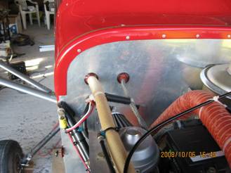
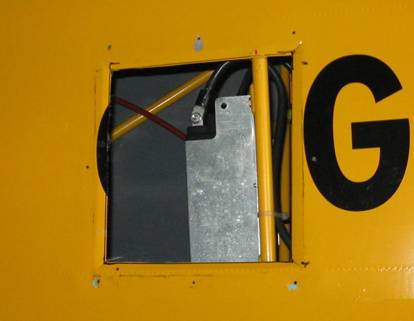
the firewall and making it accessible from beneath the panel. Here is a picture
of a typical firewall at the top right side with starter solenoid, regulator,
capacitor and fuse all on the engine side as per manual:
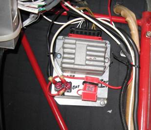
Next is a firewall with most of the electrical inside:
And here is what is behind the firewall:
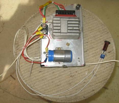
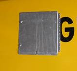
Below
is another similar panel that will mount behind the instrument panel. You can see
the two red power wires (R and B+) combined with the green C line at the top
fuse post. The charge indicator lamp is connected to the same fuse post; the other side of
the lamp goes to the L terminal at the regulator. Also the +ve side of the
capacitor goes to the same post. The -ve side of the capacitor goes to the
ground bus on the other side. The lower terminal of the fuse goes to the +ve
buss and fuses on the other side of the panel where the battery lead from the
master switch will also end up..
The
two yellow leads from the engine will go into the right side of the connector.
They come with enough length to get 8” or so aft of the firewall.
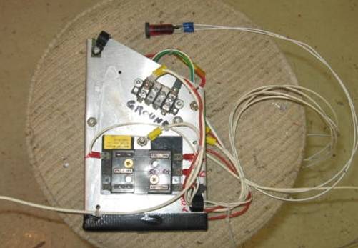
This
next picture shows the other side. There is an automotive fuse block with lines
going off bottom right to switches for radios, instruments, accessories etc.
When mounted in the plane, the main #10 line from the master switch will also
go to this bus. The smaller bus at the
top is for ground connections. The ground bus is electrically connected to the
plate and that #10 wire bottom left goes to the frame for ground. The regulator
itself calls for mounting on a grounded surface.
b.
The starter
solenoid is commonly mounted on the engine side of the firewall but there is no
significant reason for having it there except that it provides a convenient
connection for generator output and the power source for appliances. If you put
the reg/rect etc behind the firewall then the starter solenoid could also go
there. Many people believe (me included) that it is best placed right at the
battery so that the #4 starter cable is not permanently hot. Placing it beside the battery would then
require a #10 wire to carry power to the main bus. In the picture above there
is no solenoid because it has been moved to the battery box.
c.
Most certified
aircraft include a contactor/solenoid for totally disconnecting the battery.
You should decide if this is important to you and, if it is, install one near
the battery. Such a contactor can break either the ground or positive cable. In
the next picture the panel beside the rear seat holds the master battery
contactor (a manual rotary switch that cuts the ground cable), the starter
switch and a boost/charging jack.
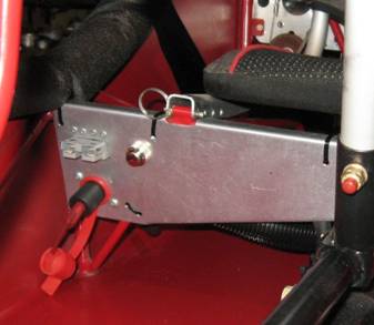
d.
A fuse or breaker
protects the subsequent cable run from burning in the event of a short. The
fuse/breaker is mounted very close to the source of power (bus) followed by a
switch, then the wire going to the appliance.
3.
Plan for a dead
battery at some point. Consider adding an accessible boost/charge plug like the
one on the top left of the above plate.
4.
Note about solenoid
contactors.
One of the reasons for going to a manual contactor
is that it requires no current to keep it engaged. Thus, if you inadvertently
left it on, the battery drain would only be due to whatever other items are
turned on; if nothing else was on, there would be no drain. If an electrical
one is used it could draw up to several amps depending on which one you chose
so, on its own, it would drain the battery.
For example, the
Rans supplied starter solenoid draws 2.7 amps; a common automotive solenoid
draws 4.0 amps; an Amco RV battery separator solenoid draws only 1.0 amps but
it may be designed to carry only a 30 amp charging load not the full starter
current load.
The function of
the master contactor is to cut off all power anywhere in the system unlike the
default wiring proposed by Rans which has the large number 4 cable always
hot from the battery all the way forward to the firewall where it goes to
one side of the starter solenoid. One compromise would be to implement the
above suggestion putting the starter solenoid at the battery, then run the # 10
wire from a 25 amp fuse at the battery to a “master switch” at the rear seat
(such as on the above pictured plate). This way, when that switch is off, there
is no power ahead of the rear seat plus it is a fused wire. This arrangement
results in much less fire hazard in a crash than the always hot, unfused # 4
cable and eliminates the constant current drain from an electric solenoid.
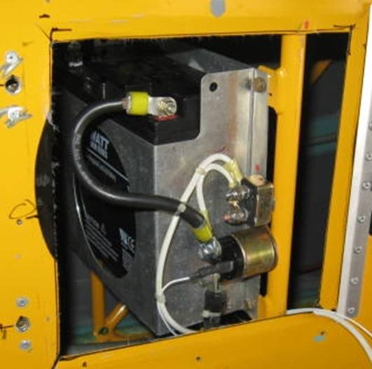
In the next
picture, an access panel has been installed beside the battery. The starter
solenoid is mounted right to the flange of the battery box as is a 25 amp
resettable automotive fuse. The short cable from the battery to the solenoid
was originally up front going from the starter solenoid to the starter. The
heavy white lines take power to the fuse then forward to a master switch. The
small white line will go to the starter switch. With this arrangement, the
number 4 cable going forward is only hot when starting. The number 10 cable
going to the master switch is always hot up to the switch which in this
installation will be beside the rear seat with the starter button.
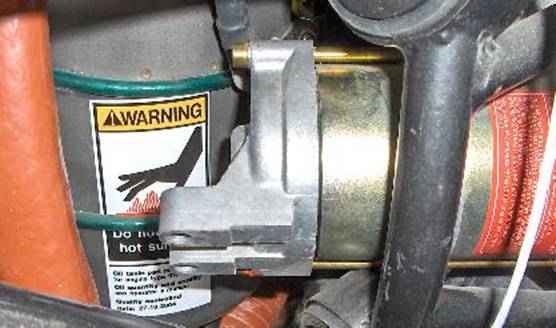
In
the picture below, the starter solenoid is bolted right to the battery post:
This PowerSonic battery has vertical, drilled lugs on the battery which make
this approach easy. Batteries like the Odyssey which have bolts going into the
top would need short 90 degree brass brackets to connect to the switches.
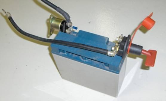
The switch on the right is a manual rotary disconnect
switch breaking the ground run. Most installations would not allow it being
mounted so close to the battery.
This is an option if you were
thinking of putting the battery right up front as some people have done.
5.
Once you have
positioned all the components, you are ready to connect them together.
Excellent
reference material on wiring is available from Bob Nuckolls at the Aero
Electric Connection. A related company, B and C Electronics, sells wiring
hardware and devices such as over voltage relays.
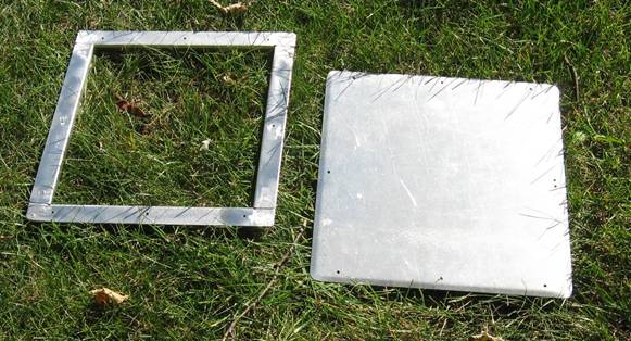
Alternative battery access hatch
Getting at the battery and the cables through the belly access
panel on a short tail or even through the side hatch on an S model is not so
easy. Here is an alternative on the right side. First you’ll need a frame to
provide support for the fabric and a base for fasteners:
Next it is glued inside to the fabric
Next the starter solenoid and a fuse for
the main power going forward will mount here.
And then the door fitted
Most
people are quite happy to position the battery in the tail of the aircraft
where Rans has provided the appropriate attachment points. The manual
adequately covers this installation. There are both benefits and concerns for
mounting it further forward as some builders have chosen to do.
Some
of the concerns over the factory location are accessibility, length of cable
runs and quality of grounding. Although there is a large battery access panel,
it is not positioned opposite the battery so it is quite difficult to get both
arms holding tools inside to install or remove cables and the retaining rod.
Mounting the battery closer to the firewall greatly simplifies access to it and
also improves the electrical characteristics by shortening cable lengths,
providing a more direct, through the firewall engine ground and potentially
reducing the number of cables and joints.
For
these reasons, more than one builder has chosen to mount the battery between
the rudder pedals. You should not
attempt to do this without carefully examining the center of gravity issues
caused by moving such a heavy item forward. One result is likely that under
some load conditions you would need to carry maybe 25lbs in the baggage
compartment. Some people have chosen to add a baggage compartment fuel tank to
handle the cg issue along with the benefit of added fuel.
Other
builders have positioned the battery beside and under the rear seat and in the
baggage compartment (in the case of a metallized baggage box).
Whether
or not you are considering repositioning the battery you may also want to think
about including a battery master cutoff (electric or manual) and where it
should be placed as well as where the most effective position for the starter
solenoid would be for your installation.
This
picture shows the stock battery box modified to provide support for the manual
master switch (made by Hella) mounted on the negative post and the stock
starter solenoid mounted on the positive post. Flanges have been bolted and
riveted to the sides to allow for securing it to the floor. The manual master
is easily reached by the pilot with the battery on the floor between the rudder
pedals.
The
starter cable coming off the solenoid goes through the firewall to the starter.
The negative cable from the manual master also goes through the firewall to one
of the drilled lugs on the back of the heavy duty starter for grounding of
starter and engine block.
The
frame is then grounded by running a smaller cable from the other started lug to
the firewall using a brass bolt through the firewall to connect to a multi
terminal ground bus bar inside. (See Bob Nuckolls articles on grounding which
use this approach) Most electronics equipment should be grounded back to this
bus. Other devices such as lights and pump can be grounded to the frame. The
next picture shows the lugs on the starter:
Ground
wires need to be the same size as the wire supplying current to the device.
Here
is a picture of a ground bus from B and C followed by a picture of the ground
cables to the starter and firewall.
Pre- S7S Topics
Exhaust Systems
Early 90's
muffler had slip joints not ball joints and was hung off the mount only. Next
iteration had 1 ball joint per pipe outboard of muffler. Next iteration had 2
ball joints per pipe between cylinder head and muffler and had a stainless
steel version (maybe they all were in this style) and were supported below.
Many people have had issues with the alignment and durability of the lower
concentric rubbers support fitting as well as water pump and firewall clearance
issues. Some of us have lengthened one or both of the front to rear stacks to
help with water pump clearance (but making firewall clearance worse). I
lengthened the right one and had to put some right to left tension on the
muffler and used a combination of springs to mount and one lower support. Not
everyone did this.